Systems
Get to know the 20|20's Systems menu.
Updated February 18, 2023
The 20|20 thinks of your implement in terms of hardware groups called "Systems," which come in two basic types: user-created and default.
User-created systems consist of hardware that works together to measure and control to a shared target. For categorization purposes, then, it makes sense to think of them in terms of the measurements they focuses on:
- Singulated Seeding measurements like SRI, Population, and Singulation
- Force measurements in pounds, like Applied Force and Force Margin
- Liquid rate measurements in gallons per acre
- Granular rate measurements in pounds per acre
- Pressure measurements in pounds per square inch
- Position measurements in inches, like Depth
By contrast, default systems – specifically, Tractor and Implement – group hardware that works at a more general level. These systems include GPS, harnessing, Cab Control Module (CCM), and other hardware that can affect your whole equipment's performance. The Implement system also includes row-level systems like SmartFirmer, if those systems can be used by the 20|20 to control other systems.
The Systems setup menu is where you go to create new systems, to add hardware to existing systems, and to configure core aspects of how each system should operate.
Table of Contents
Create a New System
To add a new system, you simply need to tap on the Add System button in the Systems menu sidebar. This will bring up a popup showing you the types of system that are available to create. Once you select one, you will be asked to give it a nickname. This name will be used throughout the 20|20 to identify your system, so be sure to choose something clear and descriptive. (The 20|20 will offer some default names to choose from, as well as a Custom button if you'd like to create your own.)
In general, you don't have to worry about choosing the "wrong" name, since it is just a nickname and does not affect the performance of your 20|20. In the future, though, certain common names may be used to help streamline customization based on common configurations. For example, creating a force application named Down Force may help the 20|20 guess that you are not trying to add any FurrowForce modules.
If you want to remove a system after creating it, simply navigate to that system in the sidebar and tap Remove at the bottom of the page.
Configure your Implement System
When you first land in the Systems menu, you should be on the Implement system. As noted above, the Implement system contains top-level hardware that affects the performance of other systems, and unlike other systems it cannot be removed.
The most important thing to set up on this page is harnessing, because without that, none of the other systems will work properly.
Configure Harnessing
To configure your harnessing, press the Harnessing button, then Add Bus Devices (even if you're not adding, but only re-configuring existing devices). You should then see a popup, where you can select the main device you want to add. For now, DBM is the only option, so select that.
On the next page, you will see three columns:
- a list of four buses that you can switch between (CAN A, CAN B, CAN C, and CAN D)
- a list of the modules on the currently selected bus
- a total count of each type of module on the currently selected bus
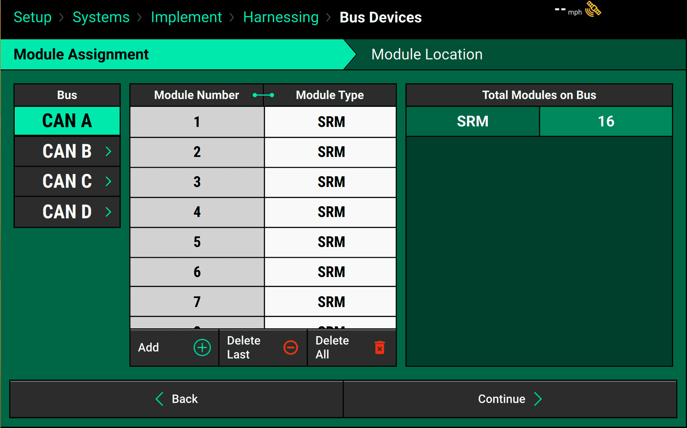
To add hardware to the current bus, press the Add button in the middle table, and select the hardware type. Then you will be asked to say how many of that module you want to add in one group before the next module type.
Although you can add modules in groups, order does matter and these are not just total numbers. For example, you cannot add all SRMs at once if there is a Smart Connector in the middle of them. You must first add the SRMs that come before the Smart Connector, then the Smart Connector, and then the SRMs that come after it.
If you make a mistake, you can either delete all of the modules on the bus, or you can just delete them one by one, starting with the last one added. (You cannot delete from the middle. To accomplish that you must delete all the way back from the end to that module, then re-add the later ones.)
Once you've got all modules added, check your work to make sure that both of the following are correct:
- the total numbers on the right
- the order of modules in the middle.
If they are, tap Continue at the bottom of the screen, and assign each module to a row. Make sure that for each bus on the left, you select it and then scroll and click through each module on that bus. When you are finished, no modules should remain with a location of "None."
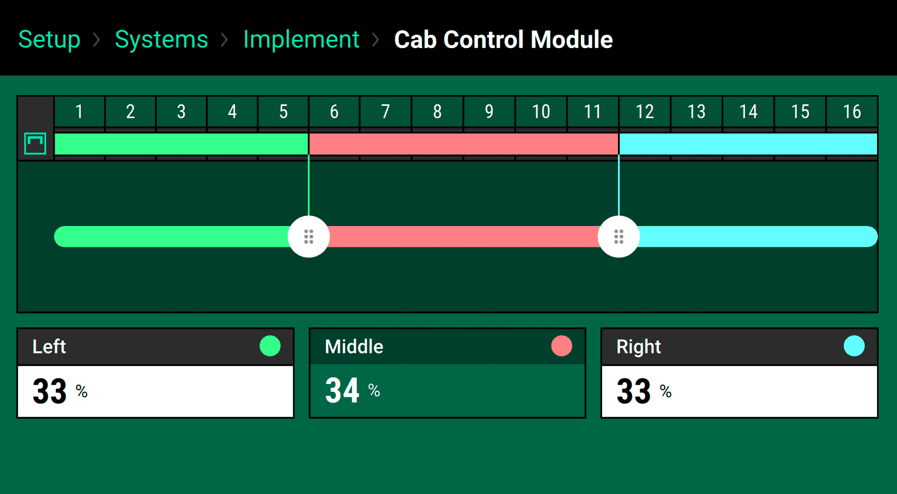
Assign Rows to Cab Control Module Section Switches
Your CCM can be used to swath on and off at the flip of a switch. To assign specific rows to each section switch, tap the Cab Control Module button on the Implement system setup menu, then either:
- Use the left and right handles to drag the slider so that each section corresponds to the right rows,
- Or use the Left and Right input boxes to assign percentages to those two sections, so that each one controls that percent of the rows, counting from the end.
Configure Outer Row Coverage
Outer Row Coverage settings simplify what earlier 20|20 software called "Swath Sections."
Sometimes you don’t want the edges of your implement to stop applying exactly when they hit previous coverage. Under some circumstances, that can lead to underplanting, especially near obstacles like trees. When that happens, you can adjust the Outer Row Coverage setting on the Implement system setup page.
What this setting does is change how sensitive the outside rows are to overlap with previous coverage:
- If you set it to Single (the suggested setting), the outside row will stop planting as usual when it crosses into previous coverage.
- If you set it to 1/2 Row Width, the outside row will stop planting when it's an extra half row deep into previous coverage.
- If you set it to Dual Ends, the outside row won’t stop applying if it crosses into previous coverage. Instead, it’ll wait until the next row crosses into coverage, then both rows will shut off at once.
Add Implement Hardware
Use the Add Hardware button to add hardware like Lift Switches, Gyros, and Motion Sensors to the implement. Once you've selected the correct hardware type, you'll be walked through a setup process. See below, under user-created systems, for more details.
Configure User-Created Systems
After creating a system, you'll want to configure its basic settings and add all associated hardware.
Configure General System Settings
There are three settings that every user-created system has:
- Active Rows are the rows that the system should be turned on for (this value is superseded by the Equipment menu setting, which will turn off all systems on the inactive rows)
- Default Rate is the fallback rate the 20|20 will use when it exits the area covered by any active prescriptions.
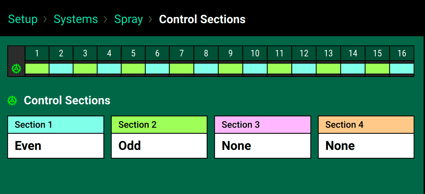
- Control Sections allow you to group rows so that they can be controlled to up to four different rates independently.
Configure System Settings Specific to Product Application
Systems that can apply product, like liquid, granular, and seeding systems, have a few additional settings:
- Coverage Overlap lets you leave an extra buffer between previous coverage and the current application, which can be sometimes make harvesting easier by leaving a gap between the end of your pass and your headlands. (In prior software versions, this was called "Row Offset")
- Coverage Pattern tells the 20|20 how to decide whether the swath section has entered a headland. If the headland isn’t perpendicular to your pass, then one row in the section will enter the headland before the other. Should the 20|20 wait until all rows in the section get to the headland to stop planting (Over-Plant in some rows)? Should it stop as soon as any row hits the headland (Under-Plant in some rows)? Or should it try to split the difference (50%-50%).
- Start/Stop Offset compensate for discrepancies if a module stops applying at the wrong time before reaching previous coverage or starts at the wrong time after leaving it. You can adjust the offset so that those line up precisely with the expected start/stop points.
- Delivery Offset tells the 20|20 where precisely the product will be hitting the field relative to the seed exit.
- CCM Autoload enables or disables the meter auto-load functionality of the CCM for the system.
Add Hardware
To add hardware to a system, simply tap the Add Hardware button and select the appropriate module type.
Depending on the type of module you're adding, you will be walked through a series of steps to do one or more of the following:
- Tell the 20|20 where the modules are physically located ("Module Locations"). You can think of this, for example, as asking which SRM has the module installed.
-
Tell the 20|20 which CAN bus connections each module location uses ("Module Connections"). This makes it possible to install multiple modules on a single SRM, for example.
If you want every location to use the same connection types, use the Apply All button after selecting the first example. You won't notice any visible changes, but the selection will transfer to all other locations.
-
Assign rows for the 20|20 to control based off of the module at each location ("Module Settings").
You may see a row-by-row or other shortcut option here that will let you more quickly configure a typical setup. Otherwise, you have to go through each module location on the left to assign rows manually.
-
Configure general settings for each module individually ("Module Settings"). Make sure you scroll to see all available options.
You have to set up each module location individually by clicking through them on the left. Changes made to one will not affect others.
After you've finished, you can always return to these settings by clicking on the button with the hardware name on the system setup page.
Once you've got the system set up, make sure to check the Diagnose page to ensure that everything is green, then head over to Calibrations to perform any necessary procedures there.
Remove Hardware
To remove hardware, simply click on the appropriate hardware button, then tell the 20|20 that it doesn't exist at any location by unselecting all previously active locations. Then press Done.