20|20 Hardware Overview
Get to know the hardware behind the 20|20 and how to install it, including the display, cab control module, and display base module.
Updated January 28, 2022
Whether you’ve just gotten a new 20|20 or are looking to better understand your old system, this article will clarify what each part of the 20|20 does and how they all work together. It will also show you how to install everything and make sure it is working properly.
Table of Contents
Understand the Components of Your 20|20
Display Base Module
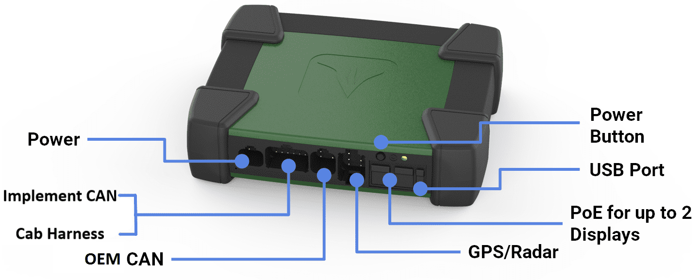
The Display Base Module, commonly called the DBM, is the engine that drives the 20|20.
It does most of the heavy-lifting data processing and storage, and it also serves as the hub that every other part of the system connects into.
To work properly, it needs to be connected to power, a display, a speed source (like GPS), and an implement CAN bus. After this initial setup, the Display Base Module requires little attention and should work quietly in the background.
Gen 3 Display
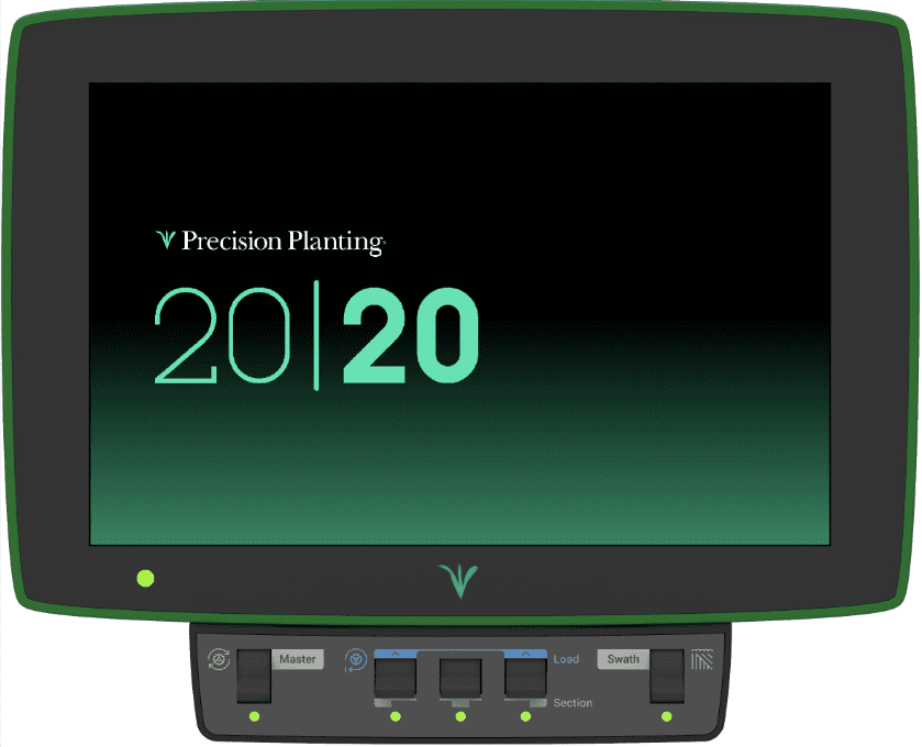
The display provides a way for you to interact with the 20|20: to configure it, view the data it collects, adjust control devices, and diagnose any problems.
It consists simply of a touchscreen, an indicator light in the lower lefthand corner, and two ports – one for an ethernet connection to the Display Base Module and another for USB – both on the left side of the display.
Cab Control Module
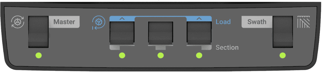
If you have control products installed, the Cab Control Module lets you enable or disable them from the cab. (If you do not have control products, you do not need a Cab Control Module.)
It consists of five switches:
- On the left, a Master switch enables and disables all control products.
- On the right, a Swath switch lets the 20|20 automatically control when the implement should plant and when it should stop planting. When this switch is off (down), the implement will always plant.
-
In the middle, three switches do double-duty:
- Each one turns on and off planting within a particular section of the implement: the left third, the middle third, and right third, respectively. When a switch is turned off (down), all rows in the corresponding section of the implement will be shut off and stop planting.
- Additionally, the outer two middle switches (marked in blue) can be used to load the seeding meters. To do that, raise these two switches up together for one second. As seed is loaded to the disk, meters will spin and dispense some seed. This allows seed to be immediately dispensed from the meter when beginning to plant.
The Cab Control Module also serves an important safety function. Because someone could be seriously injured if control products were accidentally turned on while they were in the way, the 20|20 disables control products by default, even if the system is powered up with the Master switch on. Each time you boot your 20|20, then, you’ll have to re-enable control products by toggling the Master switch (on → off → on). This protocol ensures that control products are only ever active when you intend them to be.
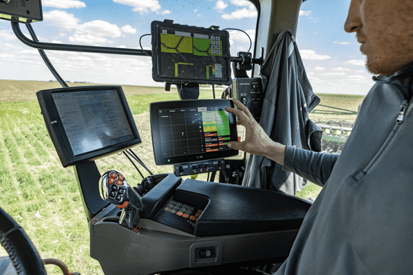
Install the 20|20 in Cab
Mount the Display
In your cab, mount the Gen 3 Display somewhere easy to see and reach so that you can make quick adjustments while out in the field.
Mount the Display Base Module
Mount your Display Base Module wherever is convenient and secure within the cab. You won’t need to interact with it during ordinary operation.
Connect Display Base Module to the Display
Once the Display Base Module is mounted, plug the provided ethernet cord into either of the two ethernet ports and connect it to the display. (There are two ethernet ports in case you want to connect a second display or FieldView module.)
Connect the Power
Connect the 725150 Power Harness to the Display Base Module in the four-pin Deutsch connector. Then connect to the cab’s power source.
Additional adapters are available if you need to connect to other types of power ports.
Connect CAN Harness
If you have a Power Distribution Module (PDM) installed, connect the implement’s CAN A harness (black connector) into the 12-pin Deutsch connector on the Display Base Module.
Otherwise, if you are only using a Smart Connector, connect it to the CAN B harness (brown connector).
The 725935 Sensor CAN harness only works with CAN B.
Place the extra cable length through the cab harness port in the back window.
Connect Speed Harness
If you are using the 20|20 for both sensing and control, connect the 725155 speed harness to the eight-pin Deutsch connector on the Display Base Module; this gives you two four-pin round connections. Then, connect to the GPS adapter and radar adapter.
If you are only using it for sensing, the 725155 adapter isn’t necessary. Just plug the 725939 harness directly into the eight-pin Deutsch connector on the Display Base Module.
Power the 20|20 On and Off
Once you have your 20|20 set up, follow these simple steps to turn it on or off.
Turn On
- Connect the power harness to the Display Base Module (DBM) and power supply.
- Turn the key on the tractor to the “on” or “run” position.
-
Switch on the power button on the Display Base Module.
The first time you turn on your 20|20, you will be asked to read and agree to the End User License Agreement. If you are setting the 20|20 up for a third party, you can agree and then later reset the agreement under the Advanced Display Settings after completing the setup.
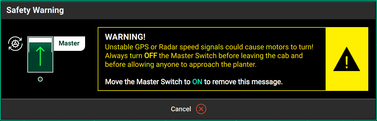
- If you have control products installed, you will need to toggle the Master switch on the Cab Control Module (on → off → on) to enable them. If you don’t, you will receive a safety warning like this. Be sure to actually toggle the switch and not just hit Cancel or your control products will remain disabled.
' width='1254' height='402' xlink:href='data:image/png%3bbase64%2ciVBORw0KGgoAAAANSUhEUgAAAEAAAAAVCAIAAAB5SH/NAAAACXBIWXMAAA7EAAAOxAGVKw4bAAAHFklEQVRIic2WeWxcRx3Hv/PseK/33vpYH%2btjvV7v2333tW9PO9k49u7Gp1qquhSHGBc5qmoMVThUrvSfUg4hCqhNi5pgKgoJbtSqcYXcAJE4xNFIkP/4H1SECBJKk0DVul00bx3bsUNwJSP600ezv5n5zczvN/ObtwPtQCE5mBUHsvFsSikW1OJALG0lC5lEIR3L2NL%2bvHyg8P5EKQ4kB7L4zMOf/MIjj3z%2bc188vrj4wNHZLz/2pU8f/9Txjy9%2bYnFxcWHBMQw5kVRF6X2IJsmSkMDE2Pjk1GTl8Oj0ffcOHRoeGxu/6%2b67K5XK2NjYR%2bbmHCel6bpuGDWomP8HLNuwUzsxFVWFp36fx%2bPxer0NDR6fz%2bfxeBoa9nm9HldpCAQC7Bbx%2b1mvl/X5OZ%2bf87vlhu71sf87mDoW2A7DsIFAAFQIFVdza9jUt4nPi442sH6wgZulq3ABNDehpXnvCbUgyOPgAOZmcGQaH76PcmSaVkdL6%2b6ifl89wzBbY9gpbidpbSE93XXJZNQ2%2b1MpyTLjtp20LcE24y3N3oAfHEc49j3AutzBIMgTgDz/XVKtkrU1Wm4oly7RLnSHw8Mjw72RiJPPvfDyS889//0zy8vfPPnU6aWlcy%2b%2buHzu3I9eWH71wqsLCw8BaG5ieA7T988fnT02O/fgkZmPzs9/7Nj8Q/fcM8OyXO0ssadSV0fLJ7%2bG6g1cf32dG39B9Rp%2btepaDObyJx59NBkXDkwcXjjz9Mypx2dOf/XYya/89crffv7Hy6u//%2b1PLl%2b6%2bvabzy0tAQg1MzyPzg7EokxvpC7RT7rDpLOTpEymu5OedaQH8T7EetEWQrgDkS50hdHduU5fFO0hhELoDFOztlZq0xlGeyvC7Yj2oLcHHe10/nAH7e2L0BQF8J0nUH0Hb1/Bu2%2bg%2bgbWrqD6Fl676AagJMVypdLWEhJzKX4ig8%2bKmIl3jw2%2bvHJ%2bdXV15ZVXzq%2bsXLx4cWpqEkCLG4AqQpMhi0hZVI/00KpjIWUiKSBloJCl/ukqsjatiglkHOTT1F7oo1VNhq1Tdw0Nlk4dTcShSlBEJPrRG6HBSCJ0eUsAb6H6Jn58Dj941tX/dTMAeu4MA6BTFwPlTP1RHaNqqJJvagttTYnab1MjGoN0VUOFbUCTEO1DSkMsiskxlA9RJyyNuljIUI8dC91dsAxkbGof60XaQs6BoaA/hlyaxp9N0dkKWegKjX9/ngZfHEBvN12xvp6WzzyB6hre/QdGDsLUcO11Wn3tZzcvcS2AdlXwHHLIERVluXE409jaAqB2uQkhDEMjaAqiqQlCjG62qSEZh6bQhfv76KbSQ%2b%2bl3seikJN0O2k6RWlLMr5uZqhUF5MQBRqGKtH8aQ2BZxHk6O60NIPj0NwMn2/zDpz8OqpVfO8ZOpsm47ETtPqbC9tOwJACE/m6SRMlPTQxePsTCKKxEabGWDqxdBKLEsd0dY1YBsk5RJWIY5O0RcQESQok0U/2F0ghRzSZFDIkHiOySJQkMXWSSzO2TmwDPq/7MdnkNpf42W/R1Bf6sa9%2b3Yerf8LlX94aQGtPV2/B7jDlDluJZk0/y246fmsKbWneeyHuzISsK7UATn0ba3/HyllceIly/gyu/Rl/%2bMWtg2qbLZhqa2fHzg/iRgBBHtlc3jS1eH%2bfqqnZrCMI/YV81rRMXVdlWTRM3U5ZTspSVVkU4vXJHiYnJ2Qx1hdRFNk0NElKxmJ96bSTdszeaETTNVWRJUlUVTXS073hfY31O/AN%2bhVau47qPynv3KB34Hc/rXnmngDN8ro6wjA%2bjm3weRlXatm/5Q6Q5ibCcyhXJg4NjRSLQ7adGRubyGRyk1MfGB%2bfKpcrhm6WSpVyZbxYHLJsJ5fJN%2bgCDthGJufYzmBxeOjg0OD%2bocGBA9nc4PjouCippfLo%2bPhEqVSZe2B%2bIJ93A2A2MqqujpannnL/v66S6nUKVark0q83Um4XCVEzCfL0S8L63QvH03TkWZpUnHsFgxw9Ip51G93epiDagwhzaHb1Rp7OEOSp0shTs5ZG8O7AIIeWJvoe6Wi7hc4OavnwgzRtzp7G8hLl7Gmc/yEeP%2bF6Rh9z7tNtl%2bL3ezjOx7FejvOy7Doc66ONbgvHennez9Oqj%2bf9rPseC6ybubjDa1V2o4XzsQEPy3oDAc82WNZTX%2b8BtkMIfW5ClWTlvYi8C0RREoSEEBcEISHJckpRdEWRdjdWvh2qqmjaTlRJEqEpiqqpe4Wma5IsjpRKR2dn752e/uCH7i9m0zOmPGGpyt6tom6uJcESFUNW/wN36Npps67okpxzMqOl8mipfHhkJKcbd%2blKSVO1/z6Vukt0hWKomiJK6Hb0rrTRlTFouY1tjRmTstNs%2bygznNJaDYliSmFHD6fN8A6b2694ZwduEkkZ0ZTRlzJ6LO3fHpJVMdH1qAUAAAAASUVORK5CYII=' /%3e%3c/svg%3e)
Turn Off
-
Switch the power button on the Display Base Module to the “off” position.
Turning the tractor off will automatically turn the 20|20 off as well. It will also turn back on when the tractor does.
Understand Indicator Light Colors
You can quickly see the status of each of your major devices — Display Base Module, Gen 3 Display, and FieldView Module — by looking at the color of their indicator lights. Use the table below to understand what each color indicates.
| Color | Display base module | Display | FieldView Module |
|---|---|---|---|
| Green | Good connectivity | Good connectivity | Good connectivity |
| White (Steady) | Initializing | N/A | Downloading software |
| White (Blinking) | Processing firmware update | N/A | N/A |
| Yellow (Steady) | Disconnected from display | Initializing | Initializing |
| Yellow (Blinking) | Processing software update | Processing software update | Processing software update |
| Blue | Missing Cab Control Module (CCM) connectivity | N/A | Nothing connected |
| Purple | Power cycle needed – turn the system off and on again | N/A | FieldView not connected |
| Red | N/A | Powering up | Powering up |
| Red (Blinking) | Failure - call Precision Support (309) 925-5050 | N/A | N/A |
Keep Software Up to Date
We’re always refining the 20|20 experience: adding new features, simplifying and clarifying old ones, and fixing minor bugs as they come to our attention. Make sure you keep your 20|20 up to date with the latest free software release so that you never miss out on anything.