Liquid
Learn how to set up and use your liquid system.
Updated January 28, 2022
Liquid systems help you monitor and control your liquid application from the cab. That way you can keep an eye on things like flow rate and pressure so that you can respond in real time, or even use a prescription and let the 20|20 do all the adjusting for you.
FlowSense, vApply Rate Control, vApplyHD, and Flow Meter can be combined in various ways or used independently to achieve the amount of control and monitoring sensitivity you want.
Table of Contents
Set Up System Hardware
Set up liquid system hardware the same way you would any other new module:
-
In the Equipment setup menu, add a new liquid system with the kind of product you’ll be applying.
- Tap Add System in the sidebar.
- Select Liquid in the popup.
- Press the Add Product button at the bottom of the page.
-
Select the product type you want to apply.
The product name you choose here is just a nickname to help differentiate liquid systems, in case you have more than one. The name does not affect any 20|20 settings or behavior.
-
In the Systems setup menu, add all hardware associated with the newly created system.
- Find the product you just added in the Systems menu sidebar. Tap it.
-
For each type of module you have,
- Press the Add Hardware button at the bottom of the page.
- Select the module type.
- Select the rows where you have installed modules.
- For FlowSense modules, select the appropriate jumper and flow path for each row, tapping on each row on the left in turn to configure it.
-
Select which rows the module should control (again tapping through each module on the left and configuring it on the right).
If you have one module per row, you can just press the Row by Row button to speed this step up.
In addition to row assignments, each module will also offer you advanced settings to adjust for fine-tuning. Two of those, for EM FlowSense, will be discussed below: Flow Rate Adjustment and Reference Value.
-
Still in the same Systems setup menu, configure any settings that apply to the system as a whole.
- Choose which rows should actively apply liquid (Active Rows).
- Specify where the application is actually happening relative to the seed exit (Application Position).
- Enter how much your liquid tank holds (Tank Size).
- Configure how the map layer is shown when entering and leaving already applied areas (Coverage Pattern).
- For systems using vApply Rate Control without vApplyHD, a Calibrations button will also appear. Press it, then press the Base Calibration button and follow the instructions.
-
In the Diagnose menu, make sure that everything is green.
- If not, troubleshoot using the usual color coding and other more system-specific diagnose information (discussed below).
-
If using Electromagnetic (EM) FlowSense, stay in the Diagnose menu to calibrate the new system.
- Select the appropriate system in the Diagnose sidebar.
- Tap on the FlowSense module name.
- Tap Zero EM FlowSense in the sidebar.
- Verify that there is liquid product in the lines but that it’s not actually flowing, then press OK.
Each time you change the product or mix being applied, you must re-zero the EM FlowSense module.
Fine Tune Advanced Settings for EM FlowSense
As noted above, there are two advanced settings that you can adjust to fine tune FlowSense operation: Flow Rate Adjustment and Reference Value. You can adjust each of these on a module-by-module basis by pressing the FlowSense button at the bottom of the appropriate system and then clicking through to the third step (shown in the image below).
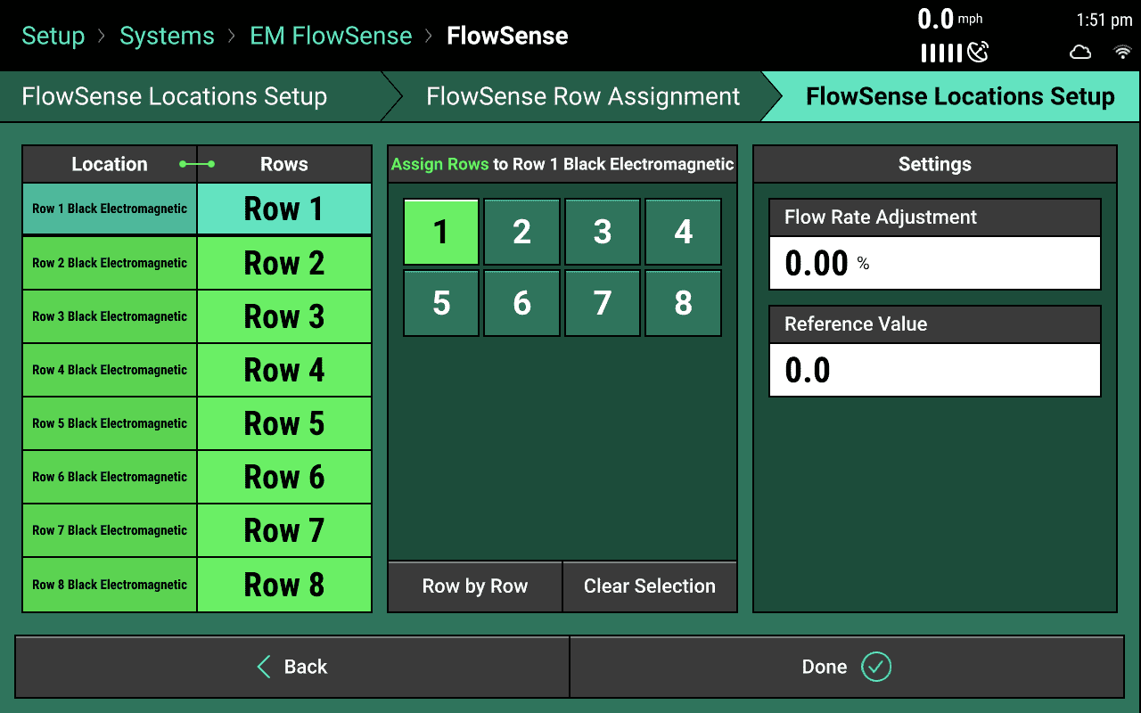
By fine-tuning the Flow Rate Adjustment, you can account for product that is more or less viscous than the average viscosity that the module was calibrated for. You are advised to do a timed catch test before changing this value in order to see exactly what flow rate you’re working with.
The 20|20 automatically calculates a Reference Value for the whole FlowSense system when you zero it during calibration. Mostly this will be sufficient for ordinary operation. But sometimes you may want to adjust individual rows. That can be done here on the third page of the FlowSense setup process.
Operate the Liquid System
Add a Control Widget to Home Screen
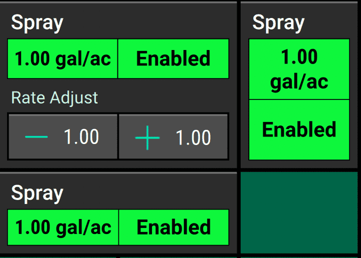
To access the control page for your liquid system, you’ll need a control widget for it on your home screen. These widgets will be labeled by the name of the system you chose during configuration (for example, Fungicide or Spray), and they are available in Wide, Tall, and Large sizes. The Large size not only serves as a shortcut to the system control page, it also lets you bump your flow target up or down easily on the go.
Once you’ve added the widget, you can tap it any time to get to the control page.
When the control system is enabled, the widget will also show the system’s currently configured flow target.
Enable the System
To enable your liquid system, go to its control page by tapping on the appropriate control widget on your home screen. (If you don’t see that widget, you may need to add it first. Remember that it will be labeled with the product nickname assigned to the system, not “EM FlowSense” or whatever module type you are using.)
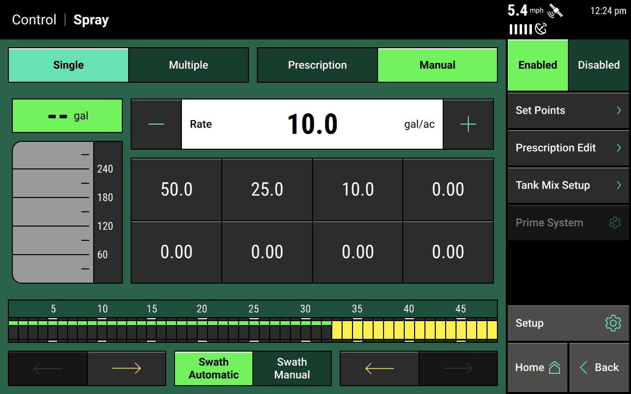
Once on the control page, press Enabled on the toggle button in the top right corner of the page.
Adjust the Target Flow Rate
You can set the target flow rate for your system on its control page.
Tap on the appropriate control widget on your home screen (or add one to it first, if necessary).
Then either:
- tap on the input box to enter a flow rate manually,
- tap on one of your preconfigured set points,
- or use the + and - buttons to increment or decrement the existing flow rate.
Add Set Points For Quick Adjustments
To make switching between specific targets easier, you can add favorite values (called set points) that will show up on the buttons in the middle of the page. Simply tap Set Points in the sidebar, and then tap any of the existing values to change them. Once you’re done, hit Back and then press any of your new set points to make them active.
Use a Prescription to Automatically Control Flow Rates
If you have a prescription with specific flow rates assigned to different parts of your field, you can use it to control your liquid system rate targets. Simply toggle the button in the upper right of the page to Prescription, then choose the appropriate prescription.
If you have not already uploaded the appropriate prescription file to the 20|20, you’ll need to do that first.
If you want to make any quick adjustments to your prescription without going back to your computer, you can use the Prescription Edit button in the sidebar.
Apply Liquid at Multiple Rates using Rate Sections
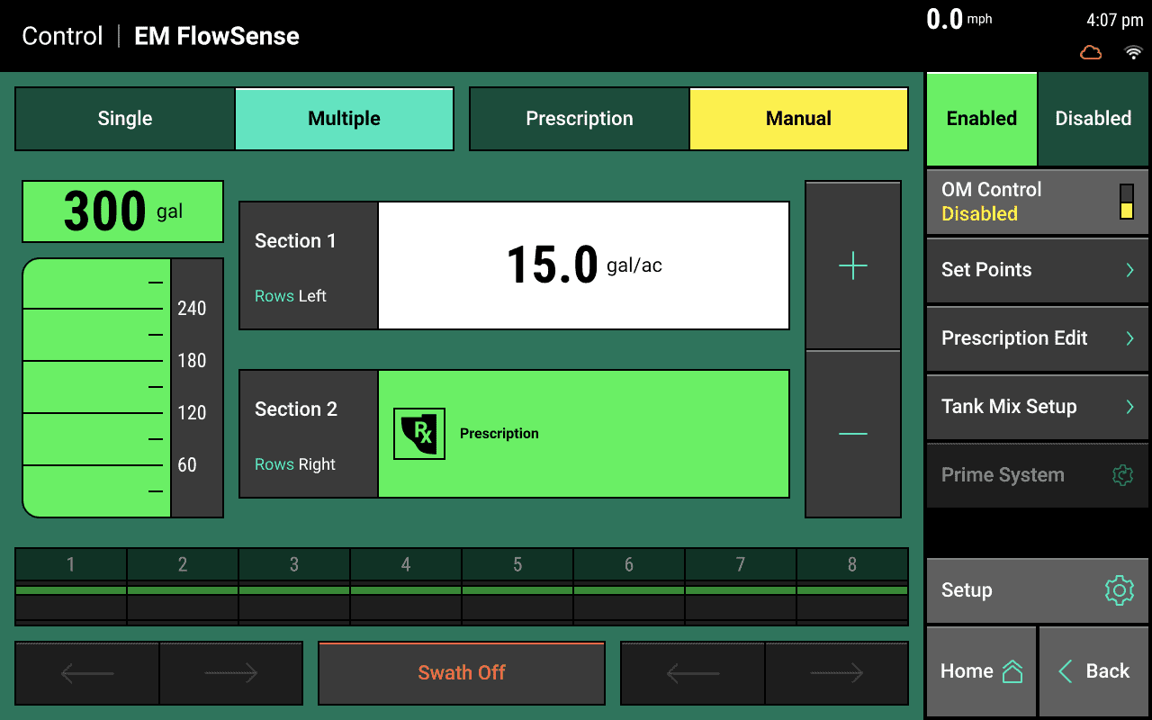
If you have multiple rate sections set up in the Systems menu, you can apply at different target rates on each section.
To do that, toggle the switch on the top left of the page by pressing Multiple. You can then configure each section independently. You can even have one section apply to a fixed target while the other one applies to a prescription, as illustrated in the image below.
Take Advantage of Tank Mixes
Liquid Tank Mixes give you fine-grained records of exactly how much of each product you’ve applied to your fields.
You can read more about how to use Tank Mixes here.
Monitor System Performance
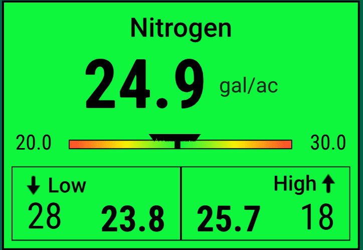
Add Metrics Widgets to the Home Screen
To keep an eye on how your liquid system is performing, you may want to add system metrics widgets to your home screen.
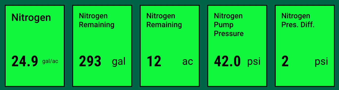
Additionally, you can configure your Dashboard Mini-Chart to show you liquid system metrics on a row-by-row basis, either all the time or on a rotating basis (swapping out other metrics at a regular interval).
View Liquid Metrics on Home Screen Map
You can also switch layers on your home screen map to show you how each row of the liquid system is performing, colored according to the alert and failure thresholds you have configured in the Crops setup menu.
Set Up Alerts and Failure Warnings
Once you’ve got your system set up, you can configure alerts and failure thresholds so that you can know immediately if it ever stops performing to your expectations.
Go to the Crops setup menu and select your system name in the sidebar.
There, you’ll find the following settings:
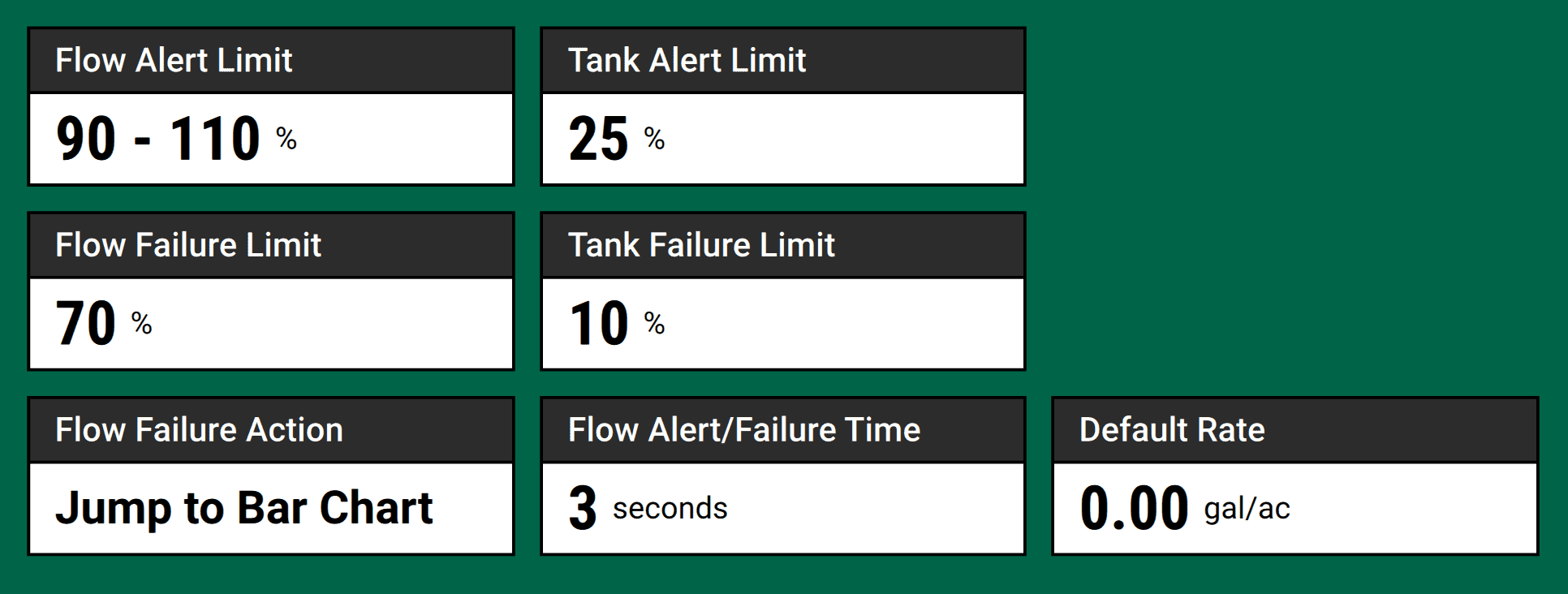
As you’ll see, you can set alert and failure thresholds for a poor flow rate and for an empty tank (if you are using the Tank Mix feature). You can also configure what the 20|20 should show you if the system fails (Flow Failure Action) as well as how long the flow rate has to underperform in order to trigger an alert or failure. Longer times will help ignore random irregularities so you can focus on systemic problems.
Diagnose and Perform Health Checks
Understand Diagnostic Metrics for vApplyHD
The vApplyHD Diagnose and Health Check pages display the following information for each module:
- Row - The row that the module is located on
- Flow - The actual flow rate measured by the module
- Flow Command - The expected flow rate, based on the target set on the system control page
- Encoder Low-Total - Pulses per second for each encoder in the module
- Ball Position - Angle in degrees
- Pressure - Pressure
- Pressure Stability - Percent
- Supply Volts – Voltage at module
Understand Diagnostic Metrics for vApply Rate Control
The vApply Rate Control Diagnose and Health Check pages display the following information for each module:
- Row - The row that the module is located on
- Flow - The actual flow rate measured by the module
- Flow Command - The expected flow rate, based on the target set on the system control page
- Pump Pressure - Pressure at the pump
- Filter Pressure - Pressure at the filter
- Duty Cycle - Percent of time the motor circuit is on
- Supply Volts – Voltage at module
Understand Diagnostic Metrics for FlowSense
The FlowSense Diagnose and Health Check pages display the following information for each module:
- Row - The row that the module is located on
- Flow - The flow rate measured by the module
- Sensor Type - Module sensor type (should say Electromagnetic when using EM FlowSense)
- Sensor Value - A metric specific to non-Electromagnetic FlowSense modules (should be empty when using EM FlowSense)
- Reference Value - Value determined when the zeroing calibration is completed (only visible when using EM FlowSense)
- Supply Volts – Voltage at module