Systems
Get to know the 20|20's Systems setup menu.
Updated February 8, 2022
After you have added a system under the Equipment setup menu, you can go to the Systems setup menu to customize it on a row-by-row level and describe how the 20|20 should use it to control the implement.
Specifically, you come here to tell the 20|20 what hardware each system consists of, where that hardware is installed, which rows each piece should control, and when to shut off a row based on previous coverage. You also calibrate and describe any relevant details about each system's overall capacity and geometry.
Additionally, this menu is where you configure a few default systems, like the Gen 3 Display itself.
If you have not already added a particular system in the Equipment setup menu, you will not be able to configure it here. Please make sure you have everything squared away in Equipment before moving on to this menu.
Table of Contents
Configure Implement-Wide Control Settings
Before adding any specific systems, you should make sure that your 20|20 is set up to control anything at all. You do this on the Systems setup menu landing page, which is labeled Control Sections in the sidebar.
Control systems will not work until you have configured both of these settings. The default settings leave control disabled.
Configure Rate Sections
The 20|20 thinks of your implement in terms of “sections,” allowing you to configure each one separately. But you get to decide which rows belong to each section and whether you even use different sections in the first place.
To do that, go to the Systems setup menu and select Control Sections in the sidebar (if that wasn’t the first page you landed on in the menu anyway).
Then, under Rate Sections, configure up to four sections by assigning rows to them.
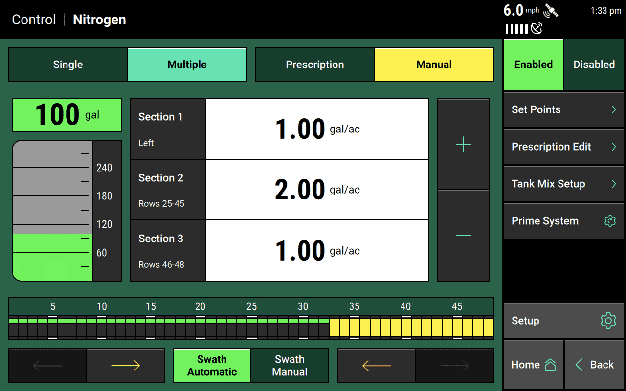
Once you’ve done that, you’ll be able to set different rates for each section on system control pages by turning on the Multiple setting, as illustrated in the image below.
Fine-Tune the Application Rules for Overlapping Edges
Sometimes you don’t want the edges of your implement to stop applying exactly when they hit previous coverage. Under some circumstances, that can lead to underplanting. When that happens, you can adjust the Control Style setting on the Control Sections setup page.
What this setting does is change how sensitive the outside rows are to overlap with previous coverage:
- If you set it to Disabled (the factory default), the implement will always keep planting regardless previous coverage.
- If you set it to Single (the suggested setting), the outside row will stop planting as usual when it crosses into previous coverage.
- If you set it to Dual Ends, the outside row won’t stop applying if it crosses into previous coverage. Instead, it’ll wait until the next row crosses into coverage, then both rows will shut off at once.
- And if those options don’t quite suit your needs, you can customize it. The Custom option will bring you to a page where you will decide how the 20|20 should break up your implement into control units. The default is row-by-row, but you can tell it to treat two rows as one (which is what Dual Ends does to the outside rows), or three rows as one, or any other combination you like. When you combine rows like this, you’re telling the 20|20 to shut them off as a unit whenever previous coverage gets to to the final row in that unit.
Add and Set Up Precision Planting Hardware
One of the primary uses of the Systems setup menu is to customize how your Precision Planting hardware is set up.
If you've got a piece of hardware that your 20|20 doesn't know about yet, you have to let it know. First, navigate to the Systems setup menu and, in the sidebar, tap the name of the system you want to assign the hardware to.
This will take you to a setup page with a chart at the top, a few input boxes below that, and an Add Hardware button at the bottom. Tap that button, then select your hardware from the list of options that pop up.
Now the display will walk you through a few configuration steps, asking you where and how the hardware is plugged in and (if applicable) which sections you want each piece of hardware to control.
Walk Through An Example
For example, let's assume we're working on a 12-row planter, and we're setting up vApply Rate Control modules that we've got installed on rows 2 and 8 via the white jumper cable. On the first page of the hardware setup, we enter this information as shown below.
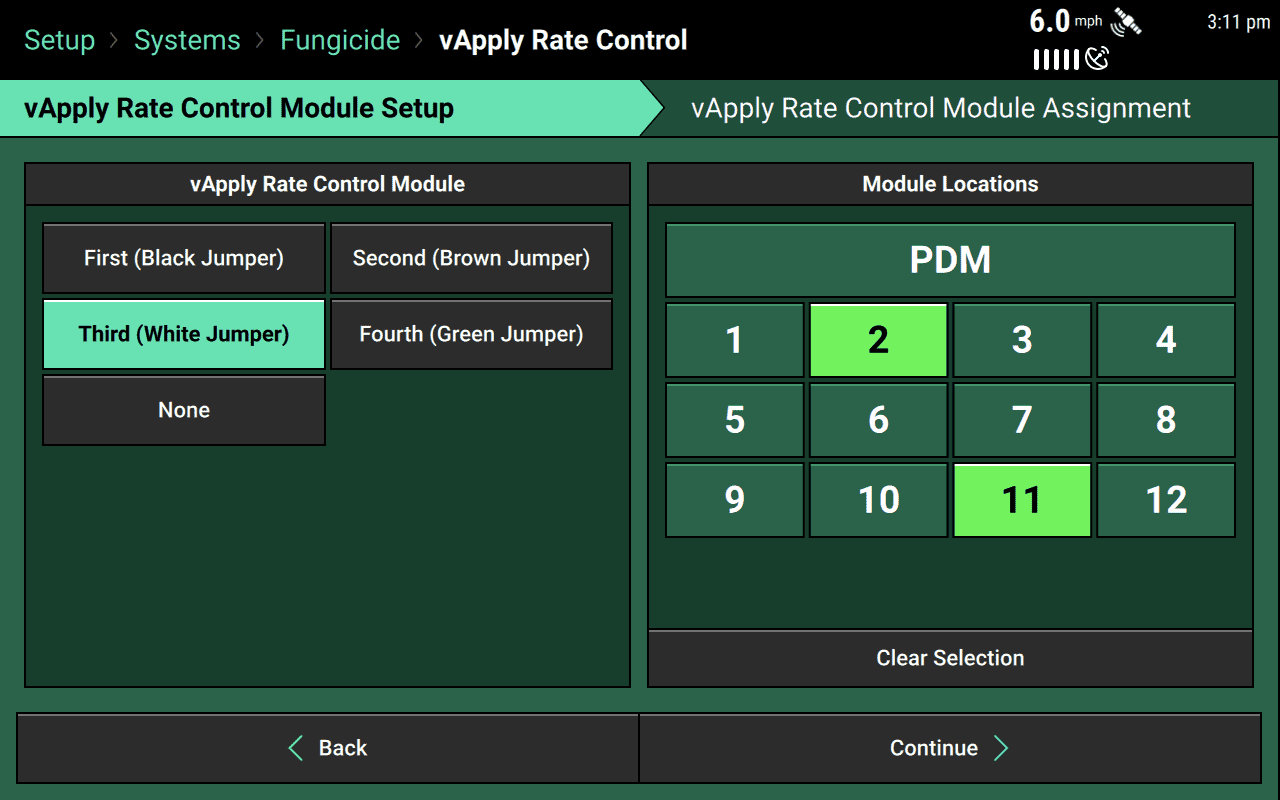
After we hit Continue, we are taken to the second step, where we tell the 20|20 which rows each module should control.
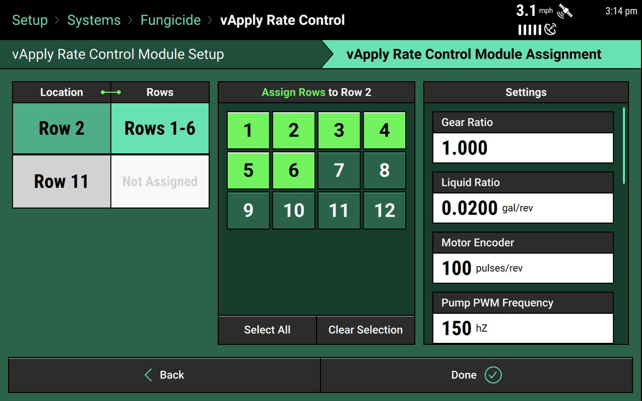
In the screenshot below, you can see that we have assigned control of Rows 1-6 to the Row 2 module. On the right, we have also adjusted settings for the Row 2 module as needed. Next we’ll tap Row 11 on the left to repeat the process for the module there.
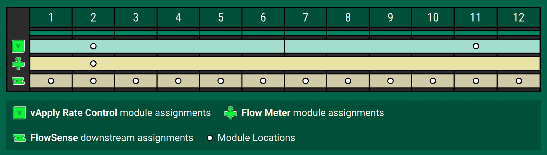
When we're done configuring the individual modules, we will be taken back to the setup page for the system that the hardware belongs to (in our case, Fungicide). There, we can see that the chart at the top of the page now has a new row corresponding to the hardware we just added.
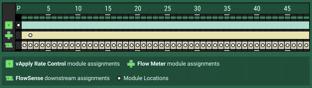
In the image below, you can see that we've also added two other types of hardware: Flow Meter and FlowSense modules. You can tell which rows correspond to which types of hardware by comparing the icon on the left against the legend below. In our case, the vApply Rate Control is at the top, and you can see that there are circles at the two row locations where we told the 20|20 to look for modules: 2 and 11. Additionally, you can see a divider line between rows 6 and 7, indicating where control is handed off from one module to the other.
If, while looking at this chart, we decide something is wrong, we can adjust it by tapping the name of the hardware at the bottom of the screen. This will take us back through the configuration steps listed above.
Sometimes, a piece of hardware will not be installed on a particular row but will instead be plugged into the Power Distribution Module (PDM). In that case, a P will appear on the lefthand side of the assignments chart, as pictured below.
Configure System-Wide Settings
Even after the 20|20 knows about all individual pieces of hardware, it will still want to know your preferences for the system as a whole. Should all rows be active? When should it stop applying as the implement crosses into previous coverage? You should answer these questions in the input boxes below the row assignments chart we looked at above.
Many of these settings are fairly self-explanatory, but a few control-based settings deserve a bit more explanation. These settings are covered in dedicated articles on each system type:
The Active Rows setting determines which rows will be active for each system. You can also set an implement-wide protocol in the Equipment setup menu, and that implement-wide protocol preempts anything here in systems.
So, for example, if you have Odd Rows active in Equipment, and your Nitrogen system is set to Even Rows active here in Systems, then your Nitrogen system will not be active during this application session.
Configure the Power Distribution Module
Make sure to configure the Power Distribution Module (PDM) so that control products can work correctly and efficiently.
We recommend that you use Gyro Only as the input source for calculating turn compensation when planting through curves (Turn Rate Source). But you also have the option of using either GPS alone or a combination of Gyro and GPS.
Next you’ll need to tell the 20|20 how the PDM is mounted: PDM Mounting Location and PDM Mounting Orientation. If you fail to do this, the system won’t be able to recognize acceleration quickly and it won’t perform as well.
Note that the directions used in setting PDM Mounting Orientation are relative to the operator sitting in the cab.
Finally, you need to calibrate the gyro. Make sure the planter is straight behind the tractor, then tap the Press to Zero button.
If the turn compensation seems off or you are getting warnings about the gyro, re-zero.
Calibrate Radar and Lift Switch
Radar and (if you are using control products) lift switch both need to be calibrated for your system to work properly. Click on each one in the Systems sidebar, press the calibration button, and follow any instructions displayed.
Configure Display Settings
The Systems setup menu is also where you go to change the settings for the 20|20 monitor: its appearance, sounds, etc.
The settings for this menu are complex enough to deserve their own article.