Down Force
Learn how to set up and use your down force system.
Updated January 28, 2022
Depending on whether you have DeltaForce solenoids installed, you can set up Down Force for monitoring alone or for control as well.
Table of Contents
Set Up a Down Force System
Set up your Down Force system the same way you would other new systems:
-
In the Equipment setup menu, add a new Down Force system.
- Tap Add System in the sidebar.
- Select Down Force in the popup.
- Press the Down Force System input in the top left.
- Select Monitor-Only if you’ve only installed load sensors or DeltaForce if you’ve also installed solenoids.
- In the popup, select your down force sensor type.
-
In the Systems setup menu, add all hardware associated with the system you just created.
- In the Systems menu sidebar, tap Down Force.
- Press the Add Hardware button at the bottom of the page.
- Select Load Sensor.
- Select the rows where you have installed sensors.
- Repeat steps b-d for solenoids, if applicable.
-
Still in the same Systems setup menu, configure any settings that apply to the system as a whole.
- Decide which rows should be active for this system (Active Rows).
- Set a Minimum Applied Force as well as a Maximum, if using DeltaForce.
-
In the Diagnose menu, make sure that everything is green.
- If not, troubleshoot using the usual color coding and other more system-specific diagnose information (discussed below).
- Still in the Diagnose menu, use the sidebar to go to Down Force, then tap Health Checks in the sidebar. Perform any health checks listed. (See below for more details about Down Force health checks.)
Operate the Down Force System
Add a Control Widget to Home Screen
To access the control page for Down Force, you’ll need a control widget on your home screen if there isn’t already one there. Once you’ve got one, you can tap it any time to get to the control page.
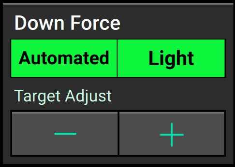
Control widgets are available in wide, tall, and large sizes for Down Force. The large size not only serves as a shortcut to the Down Force control page, it also lets you bump your target pressure up or down easily on the go.
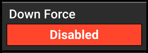
When the Down Force system is enabled, the control widget will also show the system’s currently configured target pressure.
Enable Down Force Control
To enable control for your Down Force system, go to its control page by tapping on the Down Force control widget on your home screen. (If you don’t see that widget, you may need to add it first.)
Then press Enabled on the toggle button in the top right corner of the page.
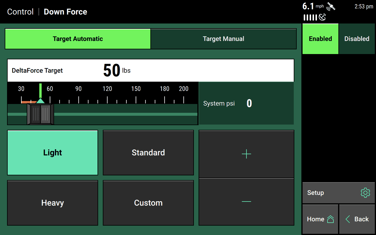
Adjust the Target Force
You have two options for controlling your Down Force system:
- setting an Automatic target
- setting a Manual target
You should default to Automatic, since that lets the 20|20 handle more of the complexity for you and to do so with greater flexibility.
Essentially, when you choose an automatic target, you’re telling the 20|20 what force you want applied, and it will try to make sure that the load sensors are always reading that force, adjusting each row on the fly, as needed, to keep hitting that target.
By contrast, if you set the force manually, you’re telling the 20|20 not to worry about what the load sensor is saying and just keep applying a constant force, equally across all rows.
Choose the control mode you want by tapping on it at the top of the page. Then select your target force, either using the slider or one of the preset options.
If you’re using a manual target, you’ll need to specify both the Lift Force and the Down Force independently.
Monitor System Performance
Add Metrics Widgets to the Home Screen
To keep an eye on how your Down Force system is performing, you may want to add a Down Force metrics widget to your home screen.
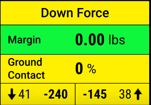
These widgets come in large or extra-large sizes, and they display four useful data points:
- Margin takes the lowest load cell reading in the last five seconds from each row and averages it across the whole implement.
- Ground Contact estimates the percentage of time the system was planting at the desired depth. In practice, that means the percentage of time where the load is at least 20 pounds.
- Low tells you the lowest weigh-pin reading on a single row, while High tells you the opposite: the highest weigh-pin reading on a single row.
Additionally, you can configure your Dashboard Mini-Chart to show you Down Force metrics on a row-by-row basis, either all the time or on a rotating basis (swapping out other metrics at a regular interval).
View Down Force Map Layers
You can also use the map on your home screen to keep tabs on Down Force system performance. There are two layers to choose from:
- Down Force maps the minimum weight measured from each load cell within the past fifth of a second. A blue stretch represents a loss of ground contact.
- Applied Down Force maps the commanded force in pounds for each row from the active Down Force system.
Diagnose and Perform Health Checks
Understand Diagnostic Metrics for Load Sensors
The Diagnose table for Load Sensors contains the following information for each row:
- Reading — the current weight measured on each individual row
- Sensor Source — the module type the load cell is plugged into (configured during setup — see above)
-
Status — the status of each load cell.
- Press this value for any row to disable (ignore) the load cell on that row or to enable it again once disabled
- If a load cell is ignored, that row will control DeltaForce to the 80th percentile of all other properly operating rows.
-
Reference Value — a value used to give a load cell a true zero
- A healthy reference value is between 28 and 36. Reference values vary across the planter; however, all should be within the healthy range. If the system suspects an issue with a load sensor, it will automatically ignore that load sensor.
- Calibration Factor — an auto-populated value based on the planter make and model selected during setup, as well as the down force sensor type
Perform Health Checks for DeltaForce
Always perform a health check on the DeltaForce system after installation and at the start of every season.
Within the Diagnose menu, go to the Down Force system and then press Health Checks in the sidebar. You’ll see two options if you have DeltaForce properly configured:
- Air Purge Test
- Advanced Applied Force Test
Understand Diagnostic Metrics for DeltaForce
As with other systems, the Diagnose and Health Check pages for DeltaForce cover the same basic information. For each row, you can see its performance in terms of:
- Load Cell — the current weight being measured on each individual row by the load cell
- Solenoid Volts — the voltage at the solenoid that controls the valve for the DeltaForce cylinder
- Commanded Pressure — the pressure that the DeltaForce system is commanding each row to apply
- Commanded Force — the weight in pounds that the DeltaForce system is commanding each row to apply (negative values represent lift while positive values represent downward force)
- Net Applied Downforce — weight that the DeltaForce system is adding to or subtracting from the weight of the row unit
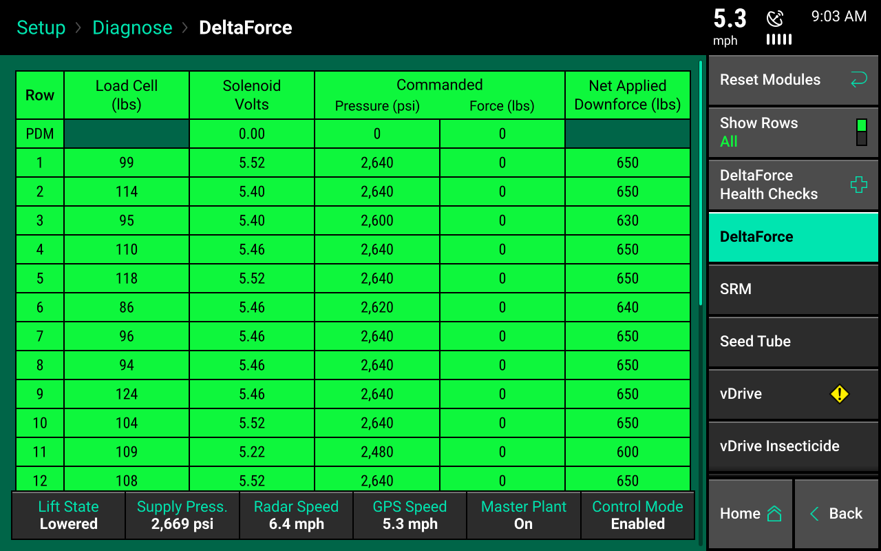
Note also the supply pressure reading at the bottom of the page (Supply Press). This is the current pressure reading on the lift valve of the lift manifold, and it must be greater than 2,250 psi for optimal DeltaForce performance.