SmartDepth Diagnostics
Ensure correct functions of SmartDepth on Diagnose Page.
Updated March 8, 2021
SmartDepth Diagnostics
Before planting, ensure all planter diagnostic information is ok:
- Select setup, and then diagnose.
- Everything should be green on the diagnose page.
- Select color legend to view an explanation of what each color indicates.
Modules may be updating during initial connection. Once updates are complete, all modules should be green. If the modules are not green, confirm that the number of rows and planter setup is correct. Still experiencing issues? Refer to the Dealer Service Manual.
Color legend
| Color | Meaning |
|---|---|
| Green | The system is working correctly and communications are good. |
| Yellow | A device or subcomponent is not running at 100 percent. |
| Red | A device has failed, or is expected, but not detected. |
| White | A device is detected, but is not expected. |
| Black | A row has been disabled in the planter configuration. |
| Gray | A device is being detected, updating firmware, or unreachable. |
SmartDepth Diagnostics
When components are powered and communicating properly with the Monitor, modules will be green on the diagnose page.
Navigate to the SmartDepth Diagnose page by selecting: Setup > Diagnose > SmartDepth.
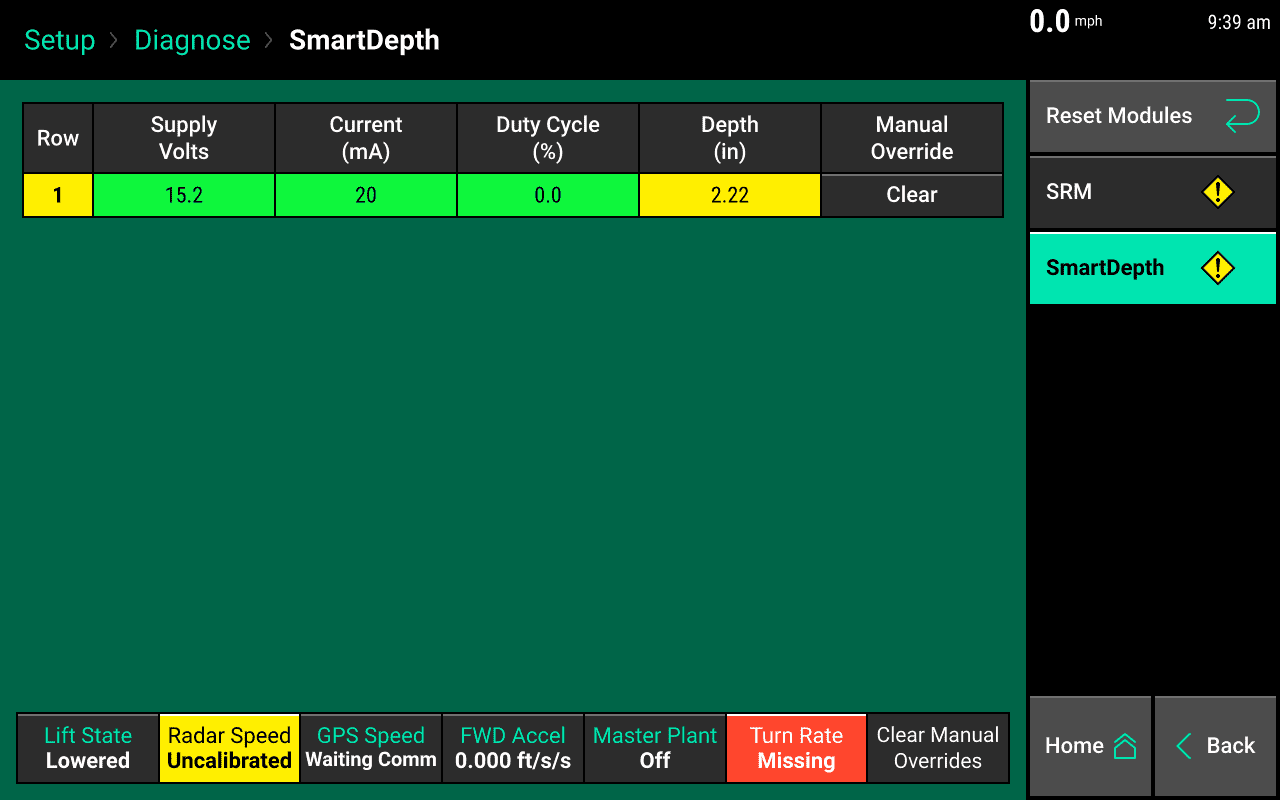
The SmartDepth Diagnostic page displays the following information for each row:
- Supply Volts – Voltage at SmartDepth Module.
- Current - Current draw on the system for SmartDepth Modules.
- Duty Cycle – Displays SmartDepth motor output over the operating range.
- Depth - The actual depth of the SmartDepth Module.
- Manual Override - Clear will appear if the button on the SmartDepth module is pressed. Clearing will return the module to be controlled by the 20|20 monitor.
Additionally: Lift State position, Radar speed reading, GPS speed reading, Forward Acceleration, Master Planter Switch position, and Turn Rate will be displayed at the bottom of the page.