DeltaForce Setup
Set up DeltaForce and adjust all settings needed.
Updated June 26, 2020
Navigate to set up DeltaForce
Go to setup and then systems, and choose DeltaForce. The default settings will function properly for most situations; adjust settings if necessary.
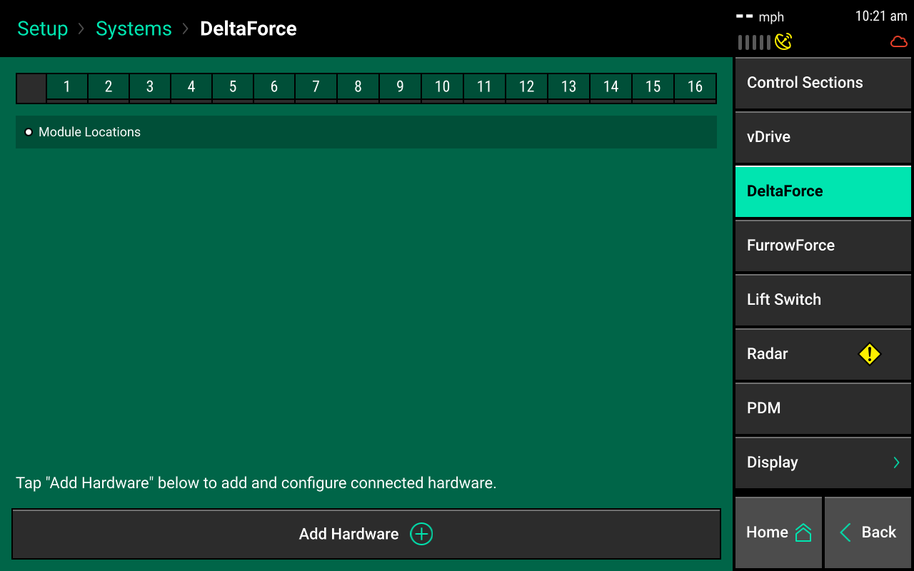
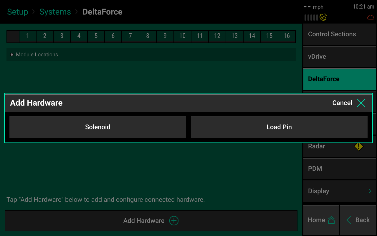
Add hardware
Press add hardware and select row installation locations for the DeltaForce solenoids and load pins.
This is only required in 2020.1.x and newer software.
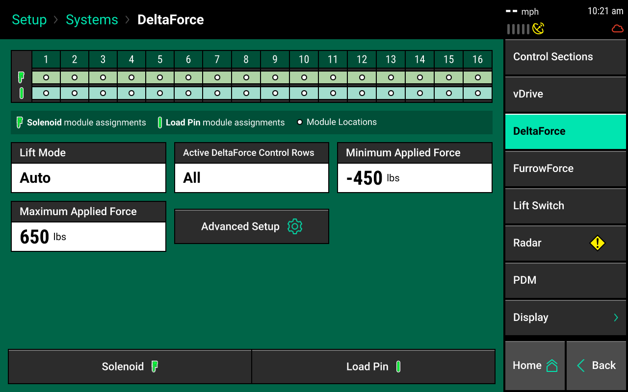
Lift mode
Choose the lift mode settings you need.
Automatic mode
Automatic mode is the default setting and the system adjusts the amount of lift force according to the needs of each row's down force. It is rare that this setting would ever need to be changed.
Manual mode
Manual mode allows you to set a consistent manual lift force while still running DeltaForce in an automatic control mode. Adjust the lift force in the DeltaForce control page. Do not use manual mode unless advised by Precision Planting Product Support.
DeltaForce cylinders must overcome the lift force to hold the row unit on the ground. Excessive manual lift targets can compromise the system's ability to maintain ground contact.
Active DeltaForce control rows
Determine the active rows for DeltaForce. This is typically only changed when DeltaForce is not installed on all rows, such as disabled rows that do not have DeltaForce installed. This applies to planters with inter-row units.
Example: A Kinze planter with pusher and puller row units contains pusher units designated as right in the monitor and puller units designated as left. On John Deere 1790 with an odd number of total rows (like 12/23 or 16/31), the corn rows would be labeled as the odd rows and the bean rows even. On the same planter with an even number of total rows (like 12/24 or 16/32), the corn rows are labeled even and the bean rows odd.
Rows that have been disabled in the planter profile will also have DeltaForce disabled and should not also be disabled in the DeltaForce systems page. For example, if the odd rows have been disabled in the planter profile and the active DeltaForce control rows is set to odd, then the even rows (every other row) of the active rows will have DeltaForce disabled.
Units
Select which unit (lbs or PSI) to display DeltaForce values. Pounds (lbs) are the default unit.
Minimum applied force
Represents the minimum amount of force that can be applied to each row unit. The default setting is -450 lbs. This value can be set from -450 to 0.
Maximum applied force
Represents the maximum amount of force that can be applied to each row unit. The default setting is 650 lbs. The value can range from 0 to 650.
Advanced setup
Contains a setting which will allow the user to disable the low pressure DeltaForce popup.
If this popup is disabled, DeltaForce will not alert the user to low pressure conditions. Low hydraulic pressure conditions will limit DeltaForce performance.
Load cells
Navigate to setup, then diagnose, to load cells. This page displays load cell information as well as control for zeroing and disabling load cells. Press zero all at the bottom of the page to zero load cell values. Ensure the planter is raised during this step.
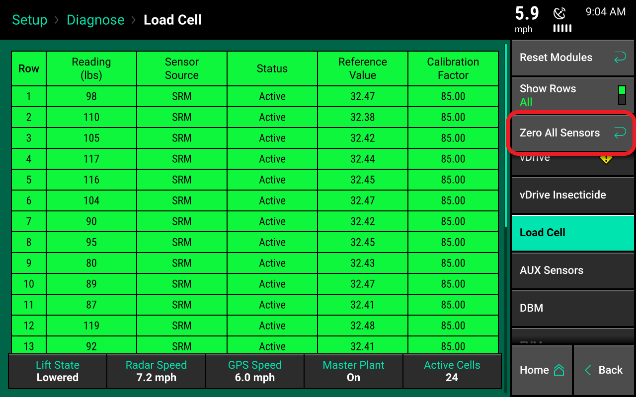
Reading (lbs)
Displays the current weight that is being measured on each individual row.
Sensor source
Identifies the type of module the load cell is plugged into.
Status
Displays the status of each load cell. Selecting a row in the status column allows the operator to ignore the load cell on that row. To make a load cell active, select that row in the status column.
Reference value
A value that is used to give a load cell a true zero. A healthy reference value is between 28 and 36. Reference values will vary across the planter, but should all be within this range.
If a load cell is ignored, that row will control DeltaForce to the 80th percentile of all other properly operating rows. If the system suspects an issue with a load sensor, it will automatically ignore that load sensor.
Calibration factor
The calibration factor will auto-populate based on the planter make and model selected and the down force sensor type.
Calibration factors for each load cell type
| Load cell | Row units | Calibration factor |
|---|---|---|
| 1/2" load pin | John Deere 7000 and Kinze 2000 row units | 85 |
| 5/8" load pin | John Deere XP row units and newer | 85 |
| Kinze link | Kinze 3000 and 4900 row units | 65 |
| White smart link | White 6000 and 8000 row units | 65 |
| White smart pin | White 9000/Precision Ready Row units | 143 |
| Case 1200 sensor | Case IH 1200 row units | 65 |
| Case 2100 sensor | Case IH 2100 row units | 196 |
| Monosem 5/8" load pin | Monosem NG+ 3 and 4 | 95 |
Lift switch
See the article on lift switch calibration and verification.
Radar
Receiving a speed reading from a tractor-mounted radar is recommended when running a control product. The radar status page allows the operator to calibrate the radar.
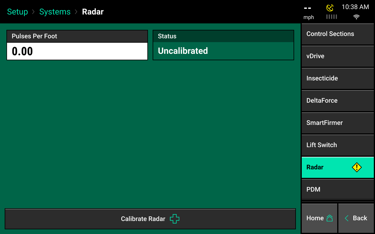
Select the calibrate radar button at the bottom of the screen and follow the onscreen instructions.
- The calibration process requires a good GPS signal.
- The operator must drive straight for at least 300 feet at a constant speed of 4 mph or more.
- If the pulses per foot is already known, enter this value manually by selecting pulses per foot.