Equipment Menu
Learn to select options to configure the planter and tractor.
Updated June 29, 2020
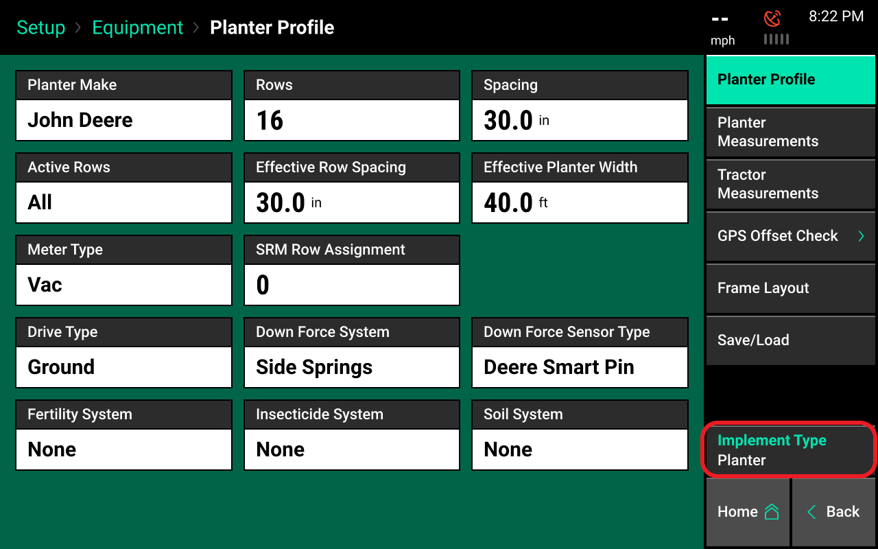
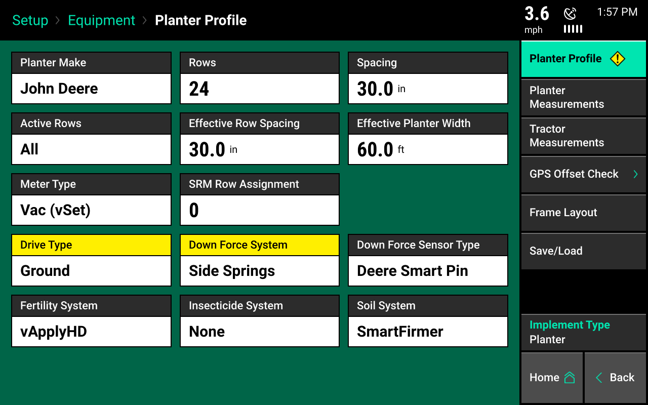
Equipment profile setup
Configure the planter and tractor. When equipment is selected from the navigation plane, each configuration for the planter that can be set displays.
Ensure all information is entered correctly in the equipment pages for accuracy.
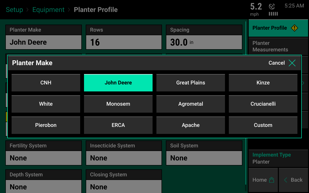
Select planter make
Press the “Planter Make” button. Select the appropriate make of the planter. Choosing the planter make will define some of the choices available in later selection screens.
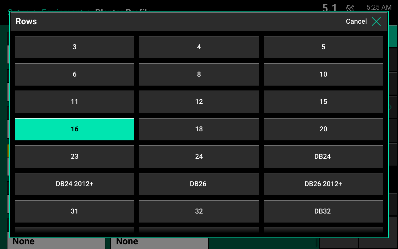
Select number of rows
Press the "Rows" button and select the correct number of physical rows on the planter. If needed, scroll for more options. There may be some options that define the year of the planter and/or the bar configuration.
If the correct number of rows is not available as an option, select "Custom" as the planter make.
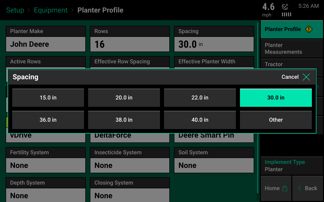
Select spacing
Press the "Spacing" button to select the row spacing for the planter.
If the correct spacing is not available, select “Other” to manually enter row spacing.
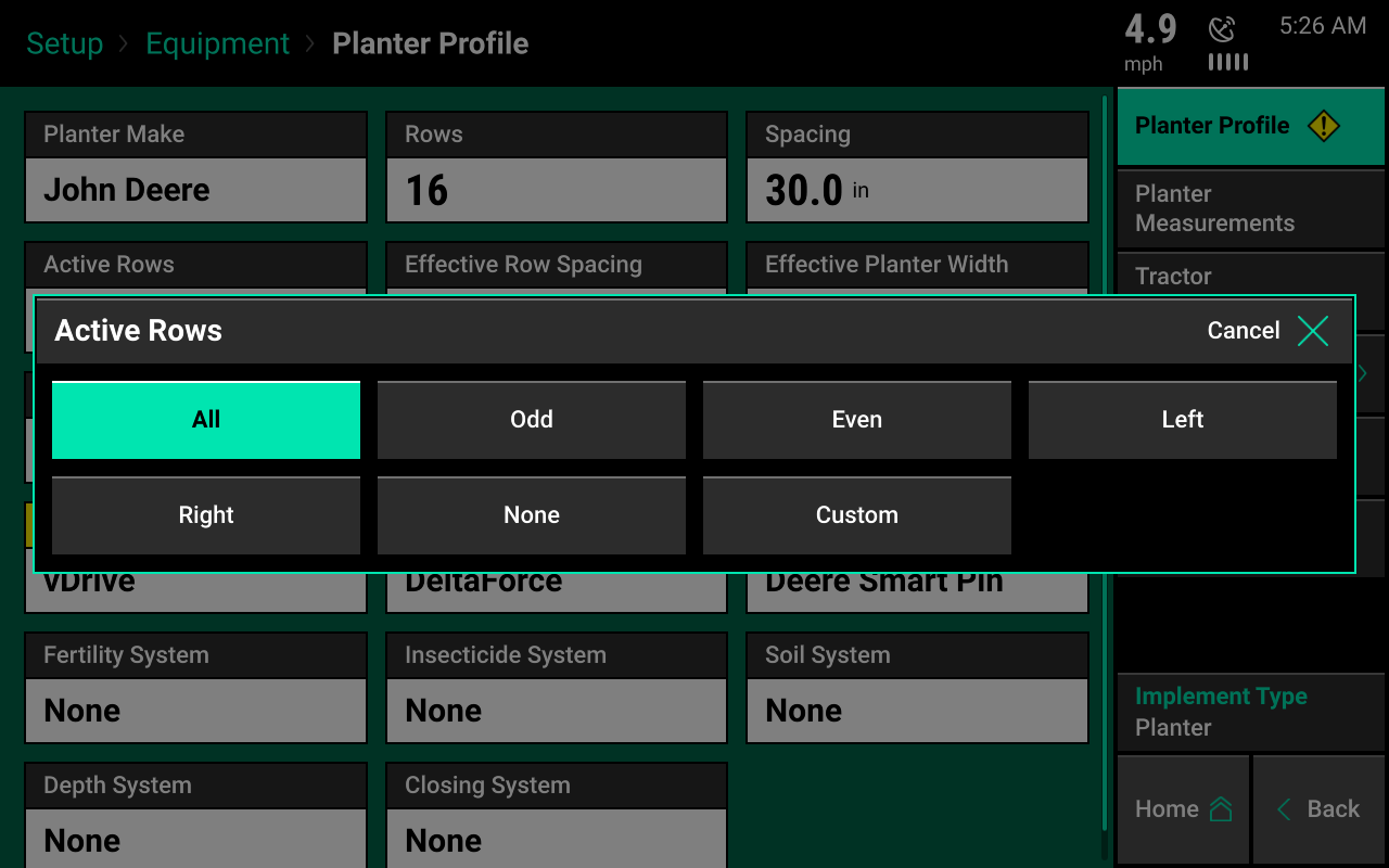
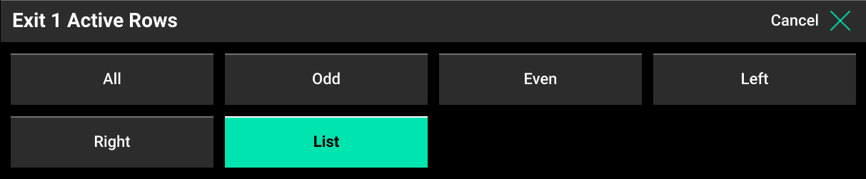
Select active rows
Pressing the "Active Rows" button defines the planter rows that will actively be planting. The system defaults to all rows active.
Preset row options:
- Odd
- Even
- Left
- Right
To define specific rows, select “List”. When listing out the active rows, rows marked by a green box are active rows.
If this is a split row planter, refer to the crops menu on how to tie active rows to each crop type the system will plant.
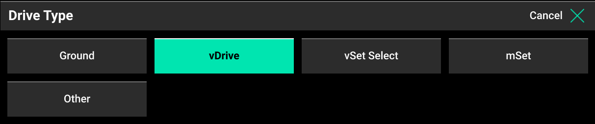
Select drive type
Press the "Drive Type" button to select the system driving the seeding. Select the correct drive type from the list. If vSet Select is the drive type, then a feed system must also be selected.
Selecting the drive type will enable control products to be set up in the systems menu.
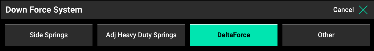
Select down force system
Press the "Down Force System" button to select the installed down force system. After selecting, a down force sensor type must be selected. Available options will depend on the chosen planter make. If you select "Custom," a calibration factor can be entered on the load cells page in the systems menu.
Selecting the down force system will enable control products to be set up in the systems menu.
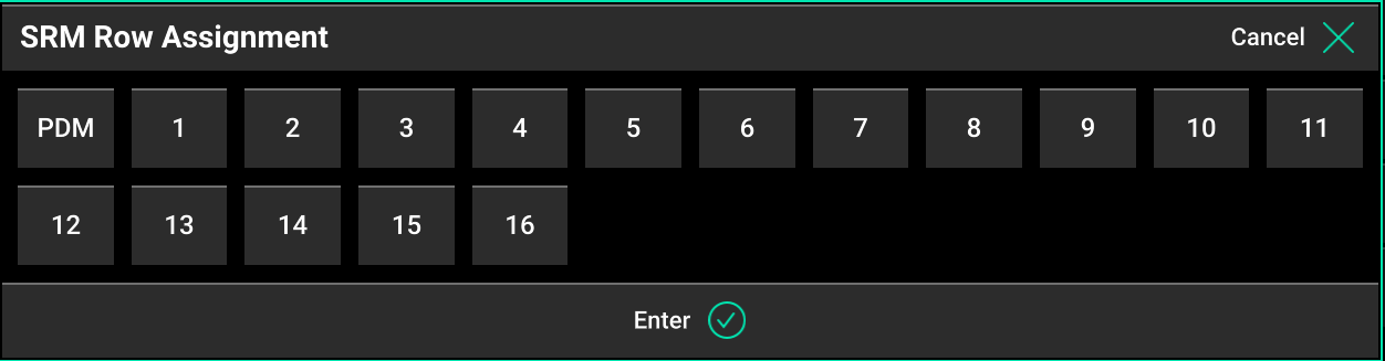
Select SRM row mapping
SRM row mapping must be selected if:
- "Ground Drive" was selected as drive type
- "Other" was selected as drive type
- DeltaForce was not selected as the down force system
Select what rows have SRMs installed, including if there is a PDM installed.
Select fertility system
Press the "Fertility System" button to select a fertility system installed on the planter.
Selecting a fertility system will enable control products to be set up in the systems menu.

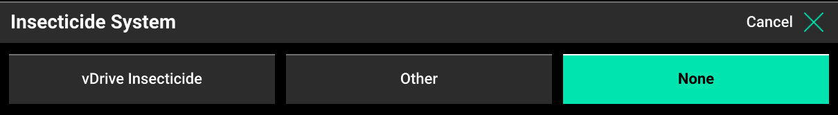
Select insecticide system
Press the "Insecticide System" button to select the insecticide system installed on the planter.
Selecting an insecticide system will enable control products to be set up in the systems menu.
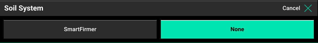
Select soil system
Press the “Soil System” button if SmartFirmers are installed on the planter. Selecting SmartFirmer enables data mapping and controls on the 20|20.
Effective row spacing
At the bottom of the page, the effective row spacing value is used for population calculations. This number is automatically calculated based on row width and active rows.
Effective planter width
Effective planter width is used for acre calculations. This number is automatically calculated based on row width, number of rows, and active rows. If either of these values is incorrect, select the button showing the values to manually enter a new value.
Planter measurements
GPS offset measurements must be set up before planting to correctly control and model the planter with the monitor.
From the home screen, select:
- Setup, Equipment, Planter Measurements
A custom table setup is available int he crops menu to enter in the exact location of each row.
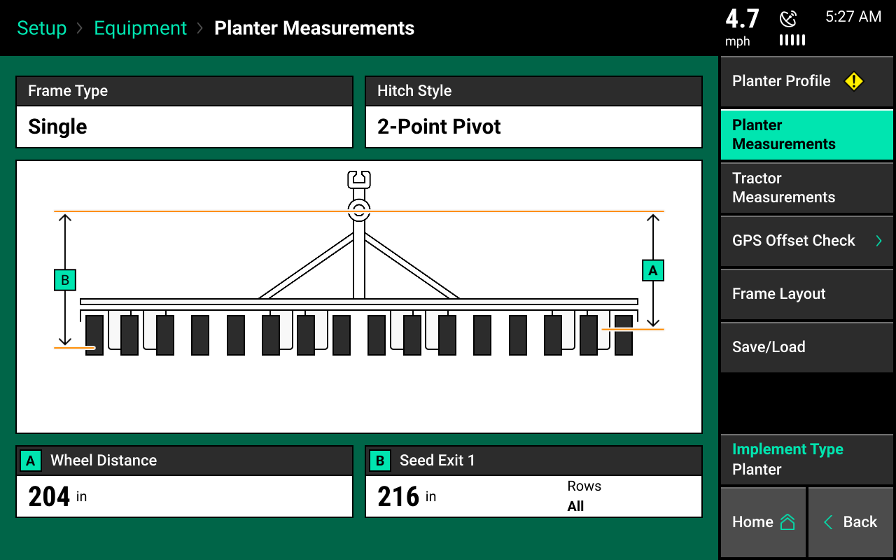
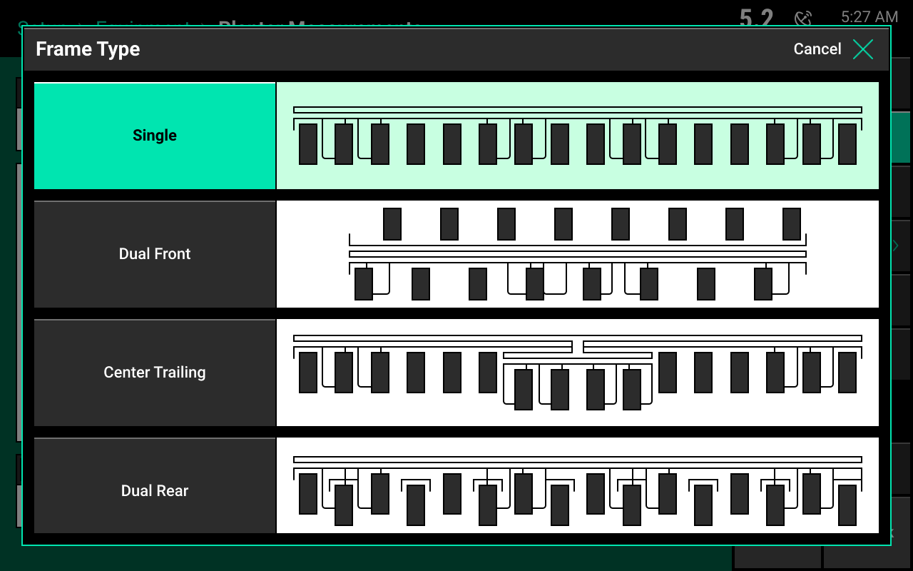
Select frame type
Select a frame type for modeling purposes. Select the frame type that best fits the planter.
- Single should be selected when all seed exits are the same distance from the planter bar.
- Dual front should be selected if the planter is a split row planter.
- Dual rear should be selected if the bar has pusher units when all rows are behind the planter bar.
- Center trailing should be selected when the seed exits of the center rows are further back than the seed exits on the planter wings.
Do not select "Center Trailing" if there are rows set back other than just the center rows. If center rows and wing rows are set back, select "Dual Rear" and define rows set back further using "Seed Exit 2."
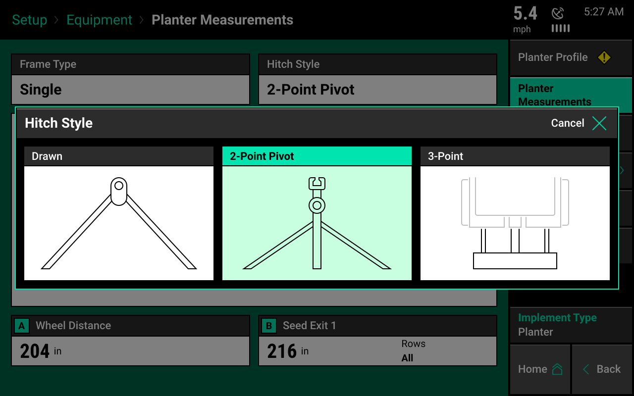
Define hitch style
Select the hitch style that best fits the planter.
Planter measurements
Depending on the frame type and hitch style selected, multiple different measurements will need to be entered into the system.
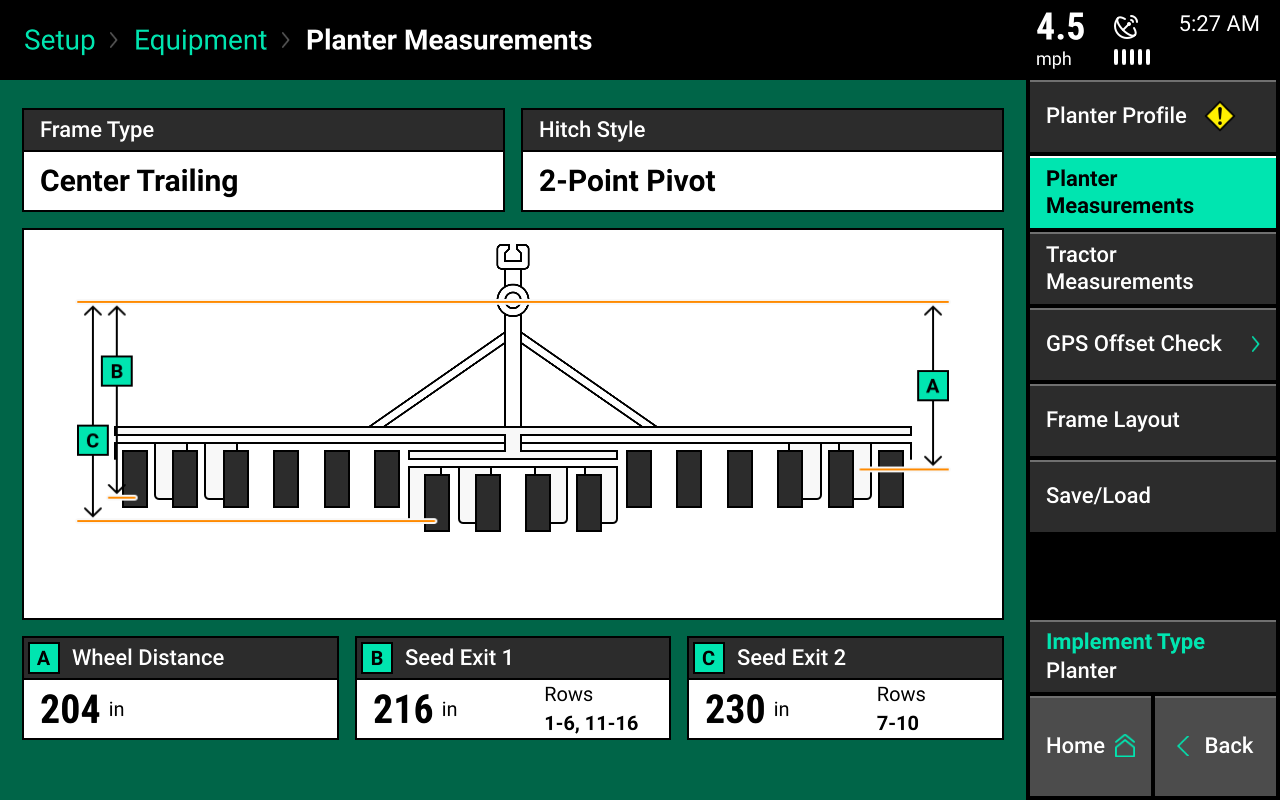
A: Wheel distance
All frame types With the planter lowered, measure the distance from the center of the drive wheels to the pivot point. Enter this measurement in box "A." Press the check mark button after entering.
For a 3-point hitch style, measure to the center of the tractor's rear axle.
B: Seed exit 1
All frame types Measure the distance from the pivot point to the seed tube exit for all rows if the frame type is single. Measure the distance to the forward-most rows for all other frame types. Enter this measurement in box "B."
For a 3-point hitch style, measure to the center of the tractor's rear axle. For frame types other than single, after entering seed exit 1 and 2 distances, define which row numbers correspond to each distance. Use "List" to manually select rows.
C: Seed exit 2
Center trailing, dual front, and dual rear frame types Measure the distance from the pivot point to the seed tube exit on the rear-most set of rows. Enter this measurement in box "C."
D: Off center distance 1
Dual front and dual rear frame types Enter the left/right offset of the forward-most rows. This is the distance from the center line of the tractor to the center of the forward-most rows. Enter this distance into box "D."
Measure from left should be selected if the rows are offset to the left side of the center line of the tractor.
Measure from right should be selected if the rows are offset to the right side of the center line of the tractor.
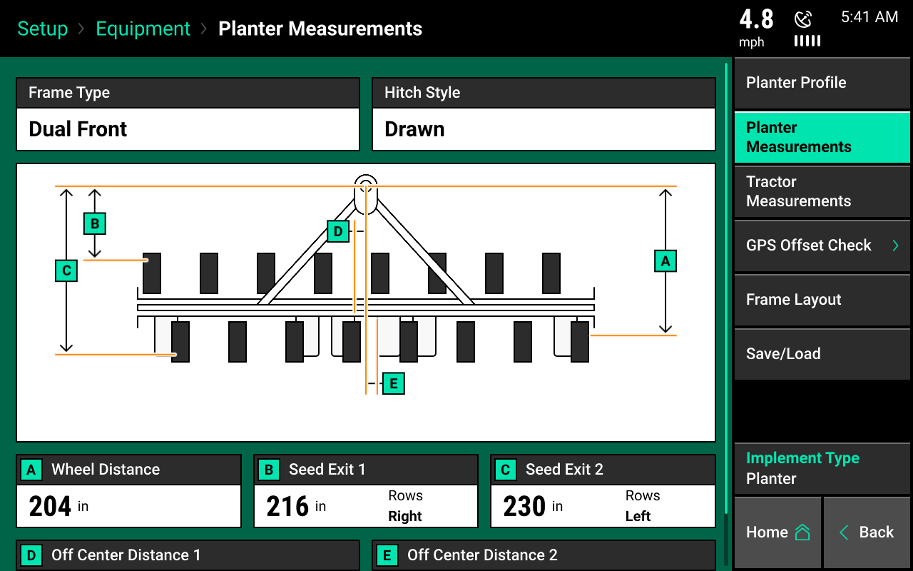
E: Off center distance 2
Dual front and dual rear frame types Enter the left/right offset of the rear-most rows. This is the distance from the center line of the tractor to the center of the rear-most rows. Enter this distance into box "E."
Measure from left should be selected if the rows are offset to the left side of the center line of the tractor.
Measure from right should be selected if the rows are offset to the right side of the center line of the tractor.
When measuring off center distances, it is possible that either distance 1, 2, or both will be zero. In this case, it does not matter if “Measure from Left” or “Measure from Right” is selected.
Tractor measurements
Set up tractor GPS measurements before planting for accurate modeling and planter control. The options for tractor make and tractor model provide useful troubleshooting information, but are not necessary to enter.
From the home screen, select:
- Setup, Equipment, Tractor Measurements
Some GPS systems do not output the location of the actual GPS globe. Verify the GPS output location with the GPS manufacturer.
Steering type
Select the steering type. Each steering has different GPS measurements to enter.
There are three steering options:
- Front
- Articulated
- Track
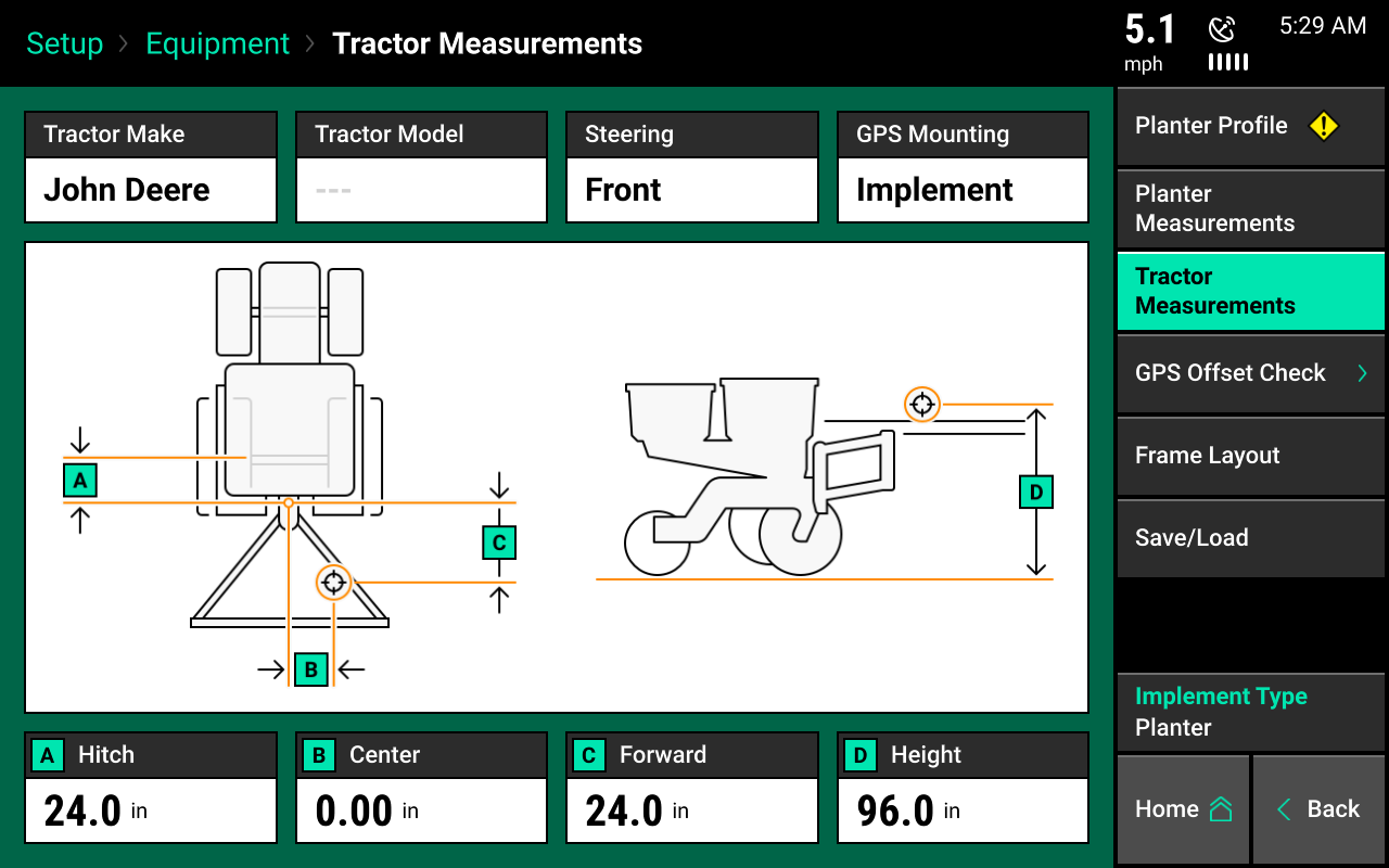
Front steering type
Find measurements for the front steering type using the image.

A: Hitch Measure the distance from the center of the rear axle to the hitch or the pivot point, if it's a two-point pivot planter hitch.
If using a 3-point planter hitch, enter "0."
B: Center Measure the distance from the center line of the tractor to the GPS output location. Then, select if the GPS output location is to the left or right side of the tractor's center line.
C: Forward Measure the distance from the center of the rear axle to the center of the GPS antenna.
D: Height Measure the distance from the ground to the base of the GPS output location.
Articulated steering type
Find measurements for the articulated steering type using the image.
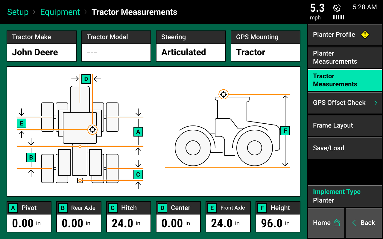
A: Pivot Measure the distance from the center of the front fixed axle to the articulation point.
B: Rear axle Measure from the articulation point to the center of the rear fixed axle.
C: Hitch Measure the distance from the pivot location at the hitch to the center of the rear fixed axle.
D: Center Measure the distance from the center line of the tractor to the center of the GPS antenna. Then, select if the GPS receiver is to the left or right side of the tractor's center line.
E: Front axle Measure the distance from the center of the front fixed axle to the GPS output location.
F: Height Measure the distance from the ground to the GPS output location.
Track steering type
Find measurements for the track steering type using the image.
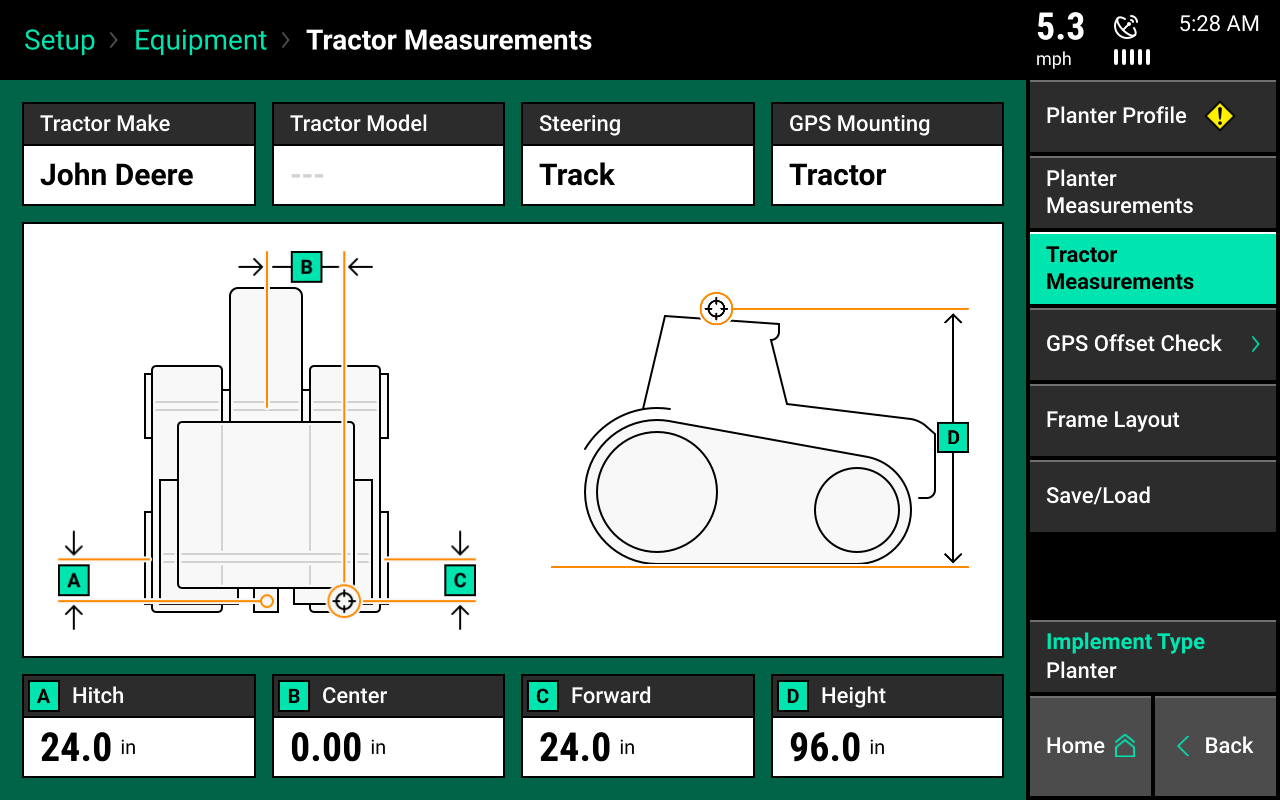
A: Hitch Measure the distance from the pivot location to the hitch or to the pivot point, if it's a two-point pivot planter hitch.
B: Center Measure the distance from the center line of the tractor to the GPS output location.
C: Forward Measure from the track pivot to the GPS output location. Indicate if the GPS output location is in the front or back of the pivot location.
D: Height Measure the distance from the ground to the base of the GPS output location.
Planter-mounted GPS
The GPS mounting location can be changed from the tractor to the planter bar. Select the "GPS Mounting" button to change the GPS measurements to allow for a planter-mounted receiver. Measurements for planter-mounted GPS systems are very similar to tractor mount GPS systems, except that measurements will be taken from the GPS output location on the planter instead of an output location on the tractor.
Verify GPS output location from the GPS manufacturer. The output location is not always the actual GPS receiver mounted on the planter. Always take measurements from the GPS output location.
GPS offset check
Once GPS measurements for both the planter and tractor are entered, a GPS offset check is required. Select "GPS Offset Check" from the navigation pane in the equipment menu.
Needed:
- A good GPS signal
- Driving on flat ground
- Front or track steering type
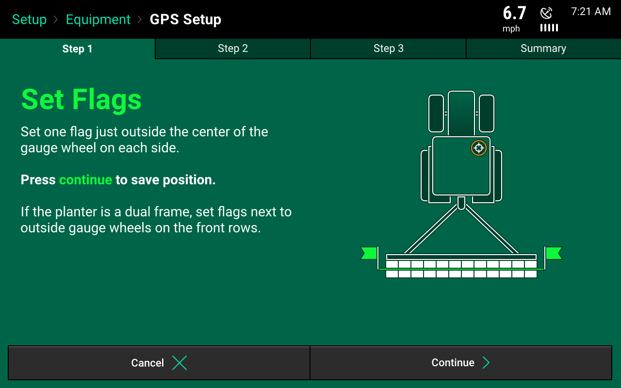
Complete offset check
Follow on-screen instructions. The check requires setting flags next to the planter's outside gauge wheels and then driving, turning around, and stopping with the gauge wheels in the same position. The tractor and planter will be facing in the opposite direction.
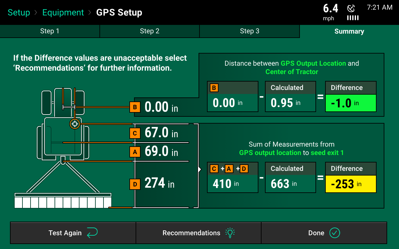
Summary page
Once the GPS offset check is complete, a summary page appears. In the top summary box, the summary shows the left/right offset. In the lower summary box, the summary shows the forward/back offset. The difference box shows how far apart the distances that were entered in the planter and tractor measurements are from calculated distances resulting from GPS offset check. This should be as close to zero as possible. The recommendations button helps determine if and what adjustments should be made.
Accuracy will also be determined by the level of correction the GPS receiver has.
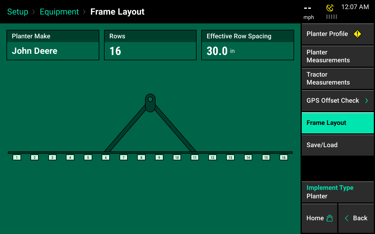
Frame layout
Ensure the planter is set up correctly through the frame layout. The image should match the physical layout of the planter. This image reflects how the 20|20 will place each row when controlling, monitoring, and mapping. If this image is not correct, adjust the planter measurements and/or custom table setup.
Save / Load
Tractor and planter configurations can be saved in the 20|20. Once a tractor and or planter has been configured (GPS measurements only) press the "Save/Load" button to save these setup configurations.
Select "Vehicles" to save tractor configurations. Select "Implements" to save planter configurations. Select the "Save Current Vehicle Configuration" button to create a name for the current configuration on the 20|20. Alternatively, choose "Save Current Implement Configuration."
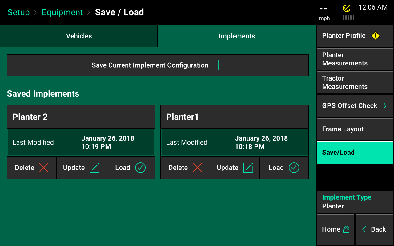
Saved configurations
Planters that are saved under the "Implements" heading saves the planter setup, GPS measurements, and all configurations for all products set up on the planter, like vDrive, DeltaForce, and more that may apply. Vehicle configurations saves all tractor and combine setup details and GPS measurements.
Configurations can be reloaded later by pressing the "Save/Load" button and then selecting the “Load” Button. This will reload a saved configuration. Delete saved configurations that no longer apply by pressing "Delete."
All configurations will be reset when you change the implement type. Using the "Save/Load" feature will allow for quick loading of previously saved configurations after changing the implement type.